AT-20 AUTOMATIC TRANSMISSION — Electric Control
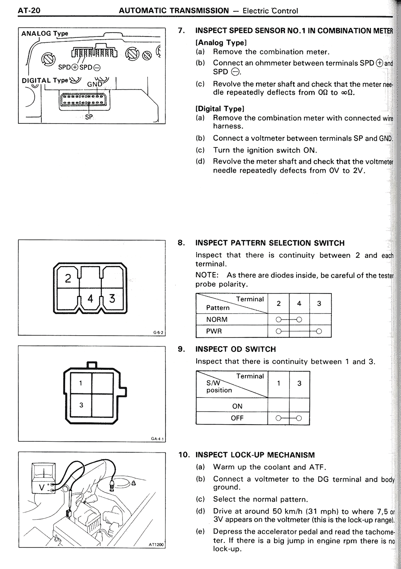
ANALOG Type
[Diagram showing SPDO/SPDO connections]
DIGITAL Type
[Diagram showing SP connection]
7. INSPECT SPEED SENSOR NO.1 IN COMBINATION METER
[Analog Type]
(a) Remove the combination meter.
(b) Connect an ohmmeter between terminals SPD ① and SPD ②.
(c) Revolve meter shaft and check that the meter needle repeatedly deflects from 0Ω to ∞Ω.
[Digital Type]
(a) Remove the combination meter with connected wire harness.
(b) Connect the meter between terminals SP and GND.
(c) Turn the ignition switch ON.
(d) Revolve the meter shaft and check that the voltmeter needle repeatedly deflects from 0V to 2V.
8. INSPECT PATTERN SELECTION SWITCH
Inspect that there is continuity between 2 and each terminal.
NOTE: As there are diodes inside, be careful of the tester probe polarity.
[Diagram showing Pattern Selection Switch with terminals 2, 4, 3]
[Table showing Terminal connections]
Pattern | Terminal | 2 | 4 | 3
NORM | ○—○ |
PWR | | | ○
9. INSPECT OD SWITCH
Inspect that there is continuity between 1 and 3.
[Diagram showing OD Switch with terminals 1, 3]
[Table showing S/W position]
S/W position | Terminal | 1 | 3
ON | |
OFF | ○—○
10. INSPECT LOCK-UP MECHANISM
(a) Warm up the coolant and ATF.
(b) Connect a voltmeter to the DG terminal and body ground.
(c) Select the normal pattern.
(d) Drive at around 50 km/h (31 mph) to where 7.5 or 8V appears on the voltmeter. (this is the lock-up range).
(e) Depress the accelerator pedal and read the tachometer. If there is a big jump in engine rpm there is no lock-up.
[Diagram showing lock-up mechanism connection labeled AT10W]