2. INSPECT DISC, PALTE AND FLANGE
Check that the sliding surface of disc is not worn or burnt.
If the disc is worn or burnt, replace all discs.
Then check that the sliding surfaces of plate and flange
are not worn or burnt.
If necessary, replace them.
NOTE: Do not allow the discs to dry out.
Prepare new discs by soaking them at least two hours in
ATF.
ASSEMBLY OF FRONT CLUTCH
(See page AT-63)
1. INSTALL NEW O-RINGS ON PISTON
2. INSTALL PISTON IN FRONT OF CLUTCH DRUM
Press the piston into the housing with the cup side up
(check ball down).
Be careful not to damage the O-rings.
3. INSTALL TWENTY PISTON RETURN SPRINGS, SPRING RE-
TAINER AND SNAP RING IN PLACE
4. COMPRESS RETURN SPRINGS AND INSTALL SNAP RING
IN GROOVE
(a) Place SST on the spring retainer, and compress the
springs with a shop press.
SST 09350-20013 (09369-20040)
(b) Install the snap ring with a screwdriver.
5. INSTALL DISCS AND PLATES WITHOUT ASSEMBLING
THINNER SNAP RING
(a) Do not assemble the thinner snap ring yet.
(b) Using low-pressure compressed air, blow all excess
ATF from the discs. For measurement of the clutch
pack, install all plates and discs temporarily without
thinner snap ring).
CAUTION: High-pressure air will damage the discs.
Install in order: Plate-disc-plate-disc-plate-disc-plate (no
snap ring)-disc
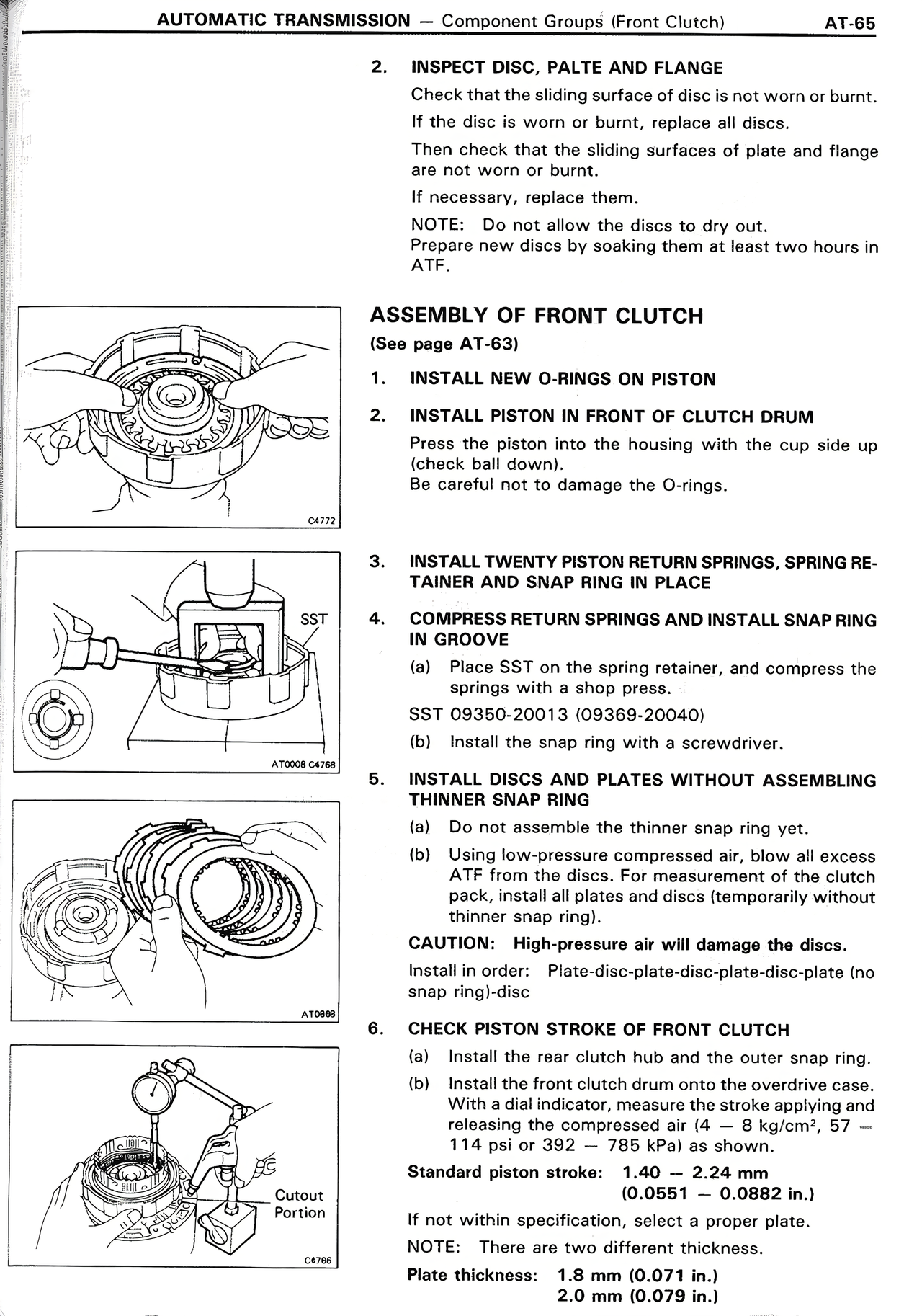
6. CHECK PISTON STROKE OF FRONT CLUTCH
(a) Install the rear clutch hub and the outer snap ring.
(b) Install the front clutch drum onto the rear clutch case.
With a dial indicator, measure the stroke applying and
releasing the compressed air (392 - 8 kgf/cm², 57 -
114 psi or 392 - 785 kPa) as shown.
Standard piston stroke: 1.40 - 2.24 mm
(0.0551 - 0.0882 in.)
If not within specification, select a proper plate.
NOTE: There are two different thickness.
Plate thickness: 1.8 mm (0.071 in.)
2.0 mm (0.079 in.)