Fuel Gauge
INSPECTION OF FUEL GAUGE
1. INSPECT RECEIVER GAUGE OPERATION
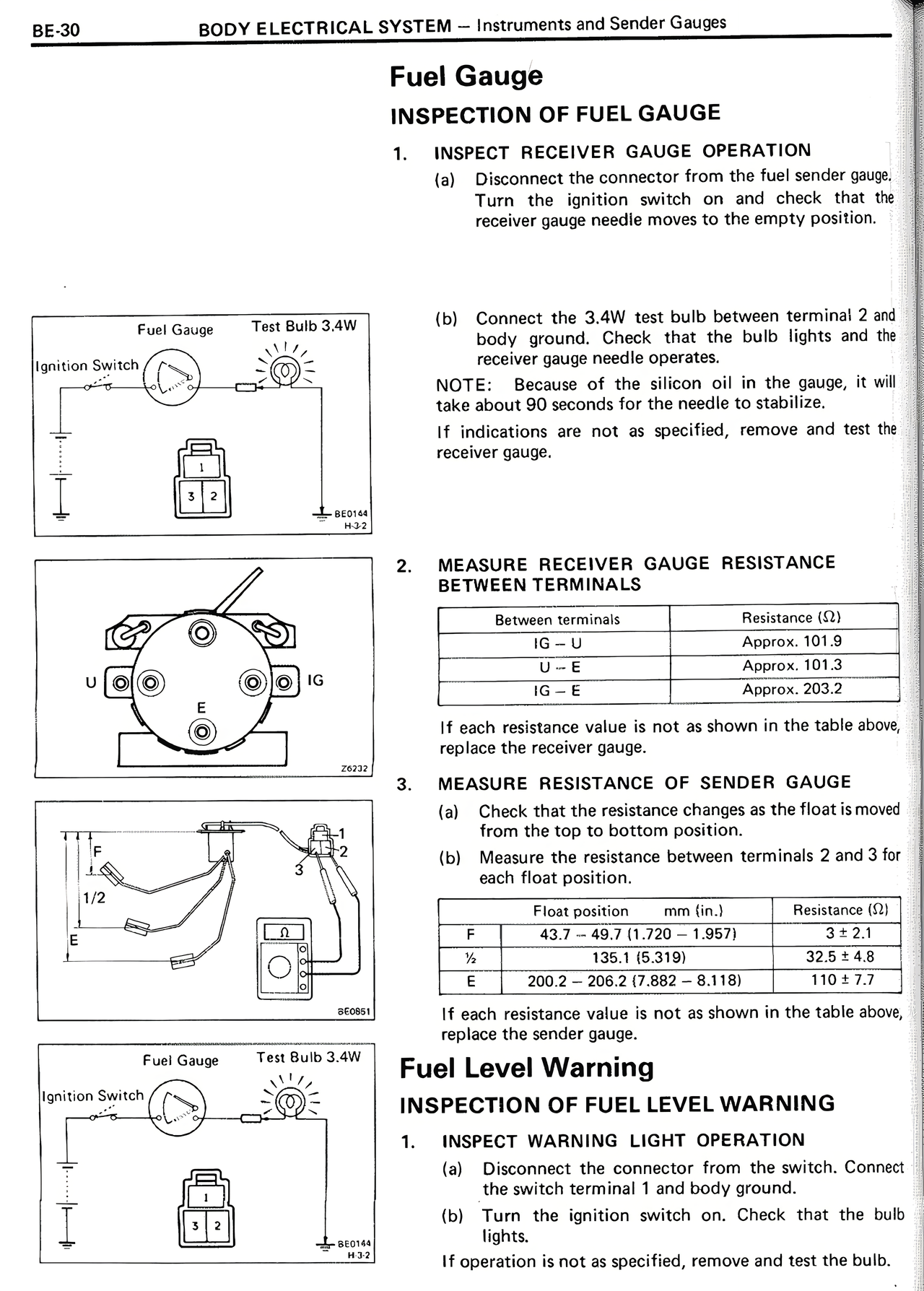
(a) Disconnect the connector from the fuel sender gauge. Turn the ignition switch on and check that the receiver gauge needle moves to the empty position.
(b) Connect the 3.4W test bulb between terminal 2 and body ground. Check that the bulb lights and the receiver gauge needle operates.
NOTE: Because of the silicon oil in the gauge, it will take about 90 seconds for the needle to stabilize.
If indications are not as specified, remove and test the receiver gauge.
2. MEASURE RECEIVER GAUGE RESISTANCE BETWEEN TERMINALS
Between terminals Resistance (Ω)
IG — U Approx. 101.9
U — E Approx. 101.3
IG — E Approx. 203.2
If each resistance value is not as shown in the table above, replace the receiver gauge.
3. MEASURE RESISTANCE OF SENDER GAUGE
(a) Check that the resistance changes as the float is moved from the top to bottom position.
(b) Measure the resistance between terminals 2 and 3 for each float position.
Float position mm (in.) Resistance (Ω)
F 43.7 ~ 49.7 (1.720 ~ 1.957) 3 ± 2.1
1/2 135.1 (5.319) 32.5 ± 4.8
E 200.2 ~ 206.2 (7.882 ~ 8.118) 110 ± 7.7
If each resistance value is not as shown in the table above, replace the sender gauge.
Fuel Level Warning
INSPECTION OF FUEL LEVEL WARNING
1. INSPECT WARNING LIGHT OPERATION
(a) Disconnect the connector from the switch. Connect the switch terminal 1 and body ground.
(b) Turn the ignition switch on. Check that the bulb lights.
If operation is not as specified, remove and test the bulb.