Door Lock Control Relay
INSPECTION OF DOOR LOCK CONTROL RELAY
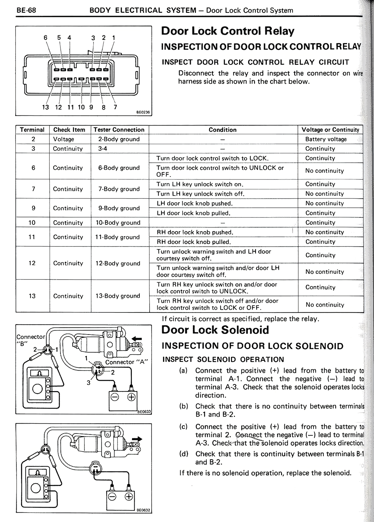
INSPECT DOOR LOCK CONTROL RELAY CIRCUIT
Disconnect the relay and inspect the connector on wire harness side as shown in the chart below.
Terminal | Check Item | Tester Connection | Condition | Voltage or Continuity
2 | Voltage | 2-Body ground | | Battery voltage
3 | Continuity | 3-4 | | Continuity
| | | Turn door lock control switch to LOCK. | Continuity
6 | Continuity | 6-Body ground | Turn door lock control switch to UNLOCK or OFF. | No continuity
7 | Continuity | 7-Body ground | Turn LH key unlock switch on. | Continuity
| | | Turn LH key unlock switch off. | No continuity
9 | Continuity | 9-Body ground | LH door lock knob pushed. | No continuity
| | | LH door lock knob pulled. | Continuity
10 | Continuity | 10-Body ground | | Continuity
11 | Continuity | 11-Body ground | RH door lock knob pushed. | No continuity
| | | RH door lock knob pulled. | Continuity
12 | Continuity | 12-Body ground | Turn unlock warning switch and LH door courtesy switch off. | Continuity
| | | Turn unlock warning switch and/or door LH door courtesy switch off. | No continuity
13 | Continuity | 13-Body ground | Turn RH key unlock switch on and/or door lock control switch to UNLOCK. | Continuity
| | | Turn RH key unlock switch off and/or door lock control switch to LOCK or OFF. | No continuity
If circuit is correct as specified, replace the relay.
Door Lock Solenoid
INSPECTION OF DOOR LOCK SOLENOID
INSPECT SOLENOID OPERATION
(a) Connect the positive (+) lead from the battery to terminal A-1. Connect the negative (—) lead to terminal A-3. Check that the solenoid operates locks direction.
(b) Check that there is no continuity between terminals B-1 and B-2.
(c) Connect the positive (+) lead from the battery to terminal 2. Connect the negative (—) lead to terminal A-3. Check that the solenoid operates locks direction.
(d) Check that there is continuity between terminals B-1 and B-2.
If there is no solenoid operation, replace the solenoid.