BE-98
BODY ELECTRICAL SYSTEM — Theft Deterrent System
Theft Deterrent Computer
INSPECTION OF THEFT DETERRENT COMPUTER
INSPECT THEFT DETERRENT COMPUTER CIRCUIT
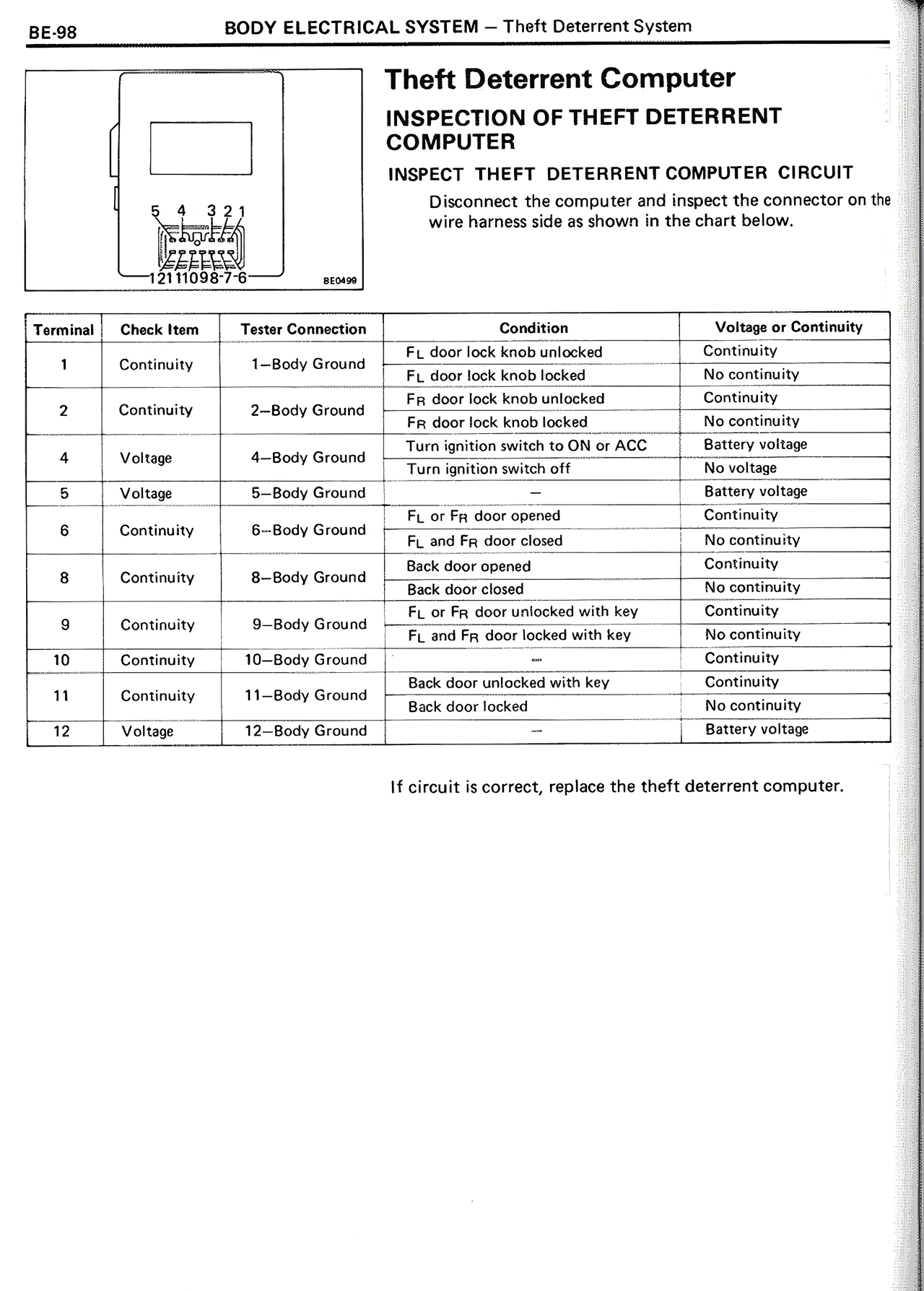
Disconnect the computer and inspect the connector on the wire harness side as shown in the chart.
[Diagram showing connector with terminals 12 11 10 9 8 7 6 5 4 3 2 1 and label BE098]
Terminal | Check Item | Tester Connection | Condition | Voltage or Continuity
1 | Continuity | 1–Body Ground | FL door lock knob unlocked | Continuity
| | | FL door lock knob locked | No continuity
2 | Continuity | 2–Body Ground | FR door lock knob unlocked | Continuity
| | | FR door lock knob locked | No continuity
4 | Voltage | 4–Body Ground | Turn ignition switch to ON or ACC | Battery voltage
| | | Turn ignition switch off | No voltage
5 | Voltage | 5–Body Ground | — | Battery voltage
6 | Continuity | 6–Body Ground | FL or FR door opened | Continuity
| | | FL and FR door closed | No continuity
8 | Continuity | 8–Body Ground | Back door opened | Continuity
| | | Back door closed | No continuity
9 | Continuity | 9–Body Ground | FL or FR door unlocked with key | Continuity
| | | FL and FR door locked with key | No continuity
10 | Continuity | 10–Body Ground | — | Continuity
11 | Continuity | 11–Body Ground | Back door unlocked with key | Continuity
| | | Back door locked | No continuity
12 | Voltage | 12–Body Ground | — | Battery voltage
If circuit is correct, replace the theft deterrent computer.