DISASSEMBLY OF ALTERNATOR
(See page CH-5)
1. REMOVE REAR END COVER
(a) Remove the nut and terminal insulator.
(b) Remove the three nuts and end cover.
2. REMOVE BRUSH HOLDER AND IC REGULATOR
Remove the five screws, brush holder, brush holder cover and IC regulator.
3. REMOVE RECTIFIER HOLDER
(a) Remove the four screws and rectifier holder.
(b) Remove the four rubber terminal insulators.
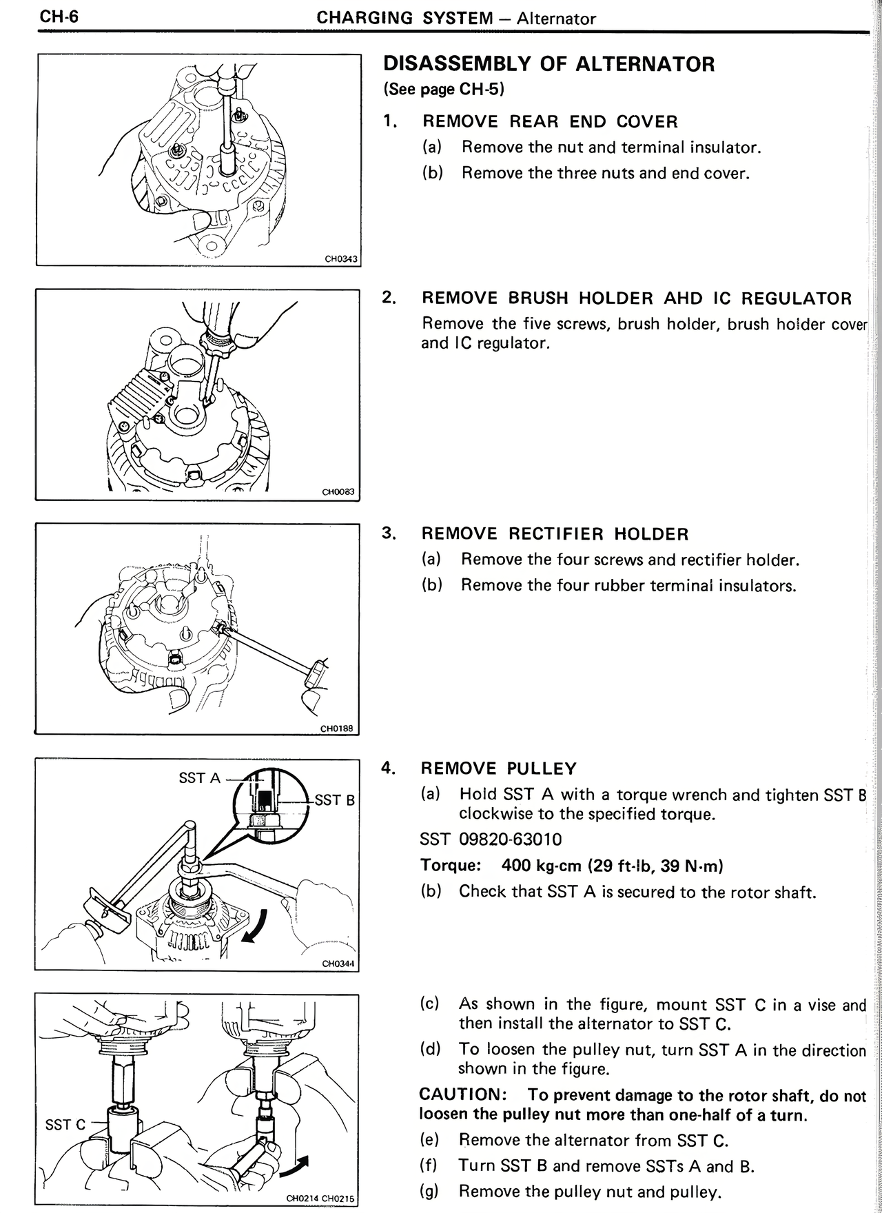
4. REMOVE PULLEY
(a) Hold SST A with a torque wrench and tighten SST B clockwise to the specified torque.
SST 09820-63010
Torque: 400 kg-cm (29 ft-lb, 39 N-m)
(b) Check that SST A is secured to the rotor shaft.
(c) As shown in the figure, mount SST C in a vise and then install the alternator to SST C.
(d) To loosen the pulley nut, turn SST A in the direction shown in the figure.
CAUTION: To prevent damage to the rotor shaft, do not loosen the pulley nut more than one-half of a turn.
(e) Remove the alternator from SST C.
(f) Turn SST B and remove SSTs A and B.
(g) Remove the pulley nut and pulley.