CLUTCH MASTER CYLINDER
COMPONENTS
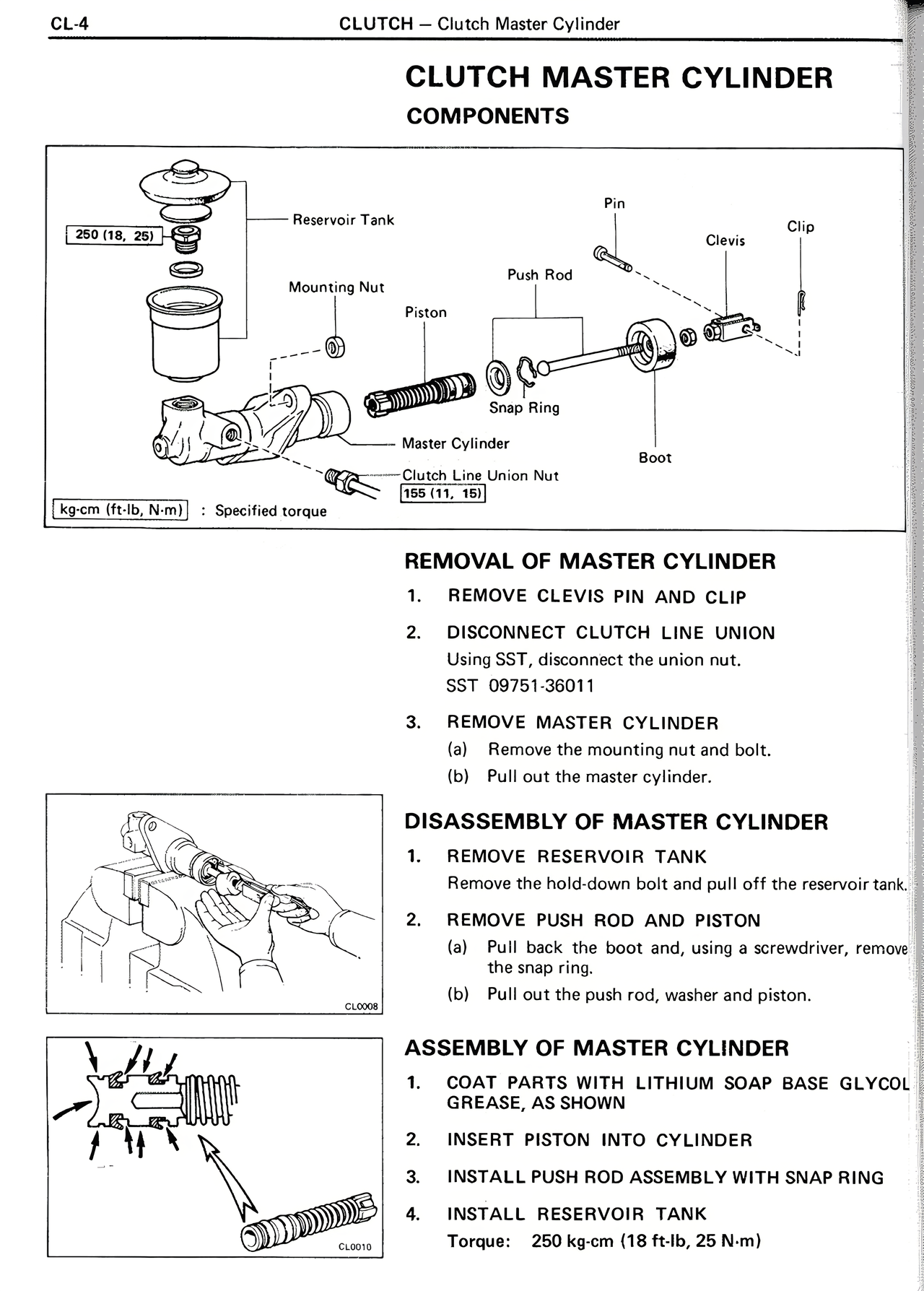
Reservoir Tank
Pin
Clip
250 [18, 25]
Clevis
Mounting Nut
Push Rod
Piston
Snap Ring
Master Cylinder
Boot
Clutch Line Union Nut
155 [11, 16]
[kg-cm (ft-lb, N-m)] : Specified torque
REMOVAL OF MASTER CYLINDER
1. REMOVE CLEVIS PIN AND CLIP
2. DISCONNECT CLUTCH LINE UNION
Using SST, disconnect the union nut.
SST 09751-36011
3. REMOVE MASTER CYLINDER
(a) Remove the mounting nut and bolt.
(b) Pull out the master cylinder.
DISASSEMBLY OF MASTER CYLINDER
1. REMOVE RESERVOIR TANK
Remove the two claws and pull off the reservoir tank.
2. REMOVE PUSH ROD AND PISTON
(a) Pull back the boot and, using a screwdriver, remove the snap ring.
(b) Pull out the push rod, washer and piston.
ASSEMBLY OF MASTER CYLINDER
1. COAT PARTS WITH LITHIUM SOAP BASE GLYCOL GREASE, AS SHOWN
2. INSERT PISTON INTO CYLINDER
3. INSTALL PUSH ROD ASSEMBLY WITH SNAP RING
4. INSTALL RESERVOIR TANK
Torque: 250 kg-cm (18 ft-lb, 25 N-m)