INSPECTION OF WIRING CONNECTOR LINE
MEASURE RESISTANCE OF ECU
CAUTION:
1. Do not touch the ECU terminals.
2. The tester probe should be inserted into the wiring connector from the wiring side.
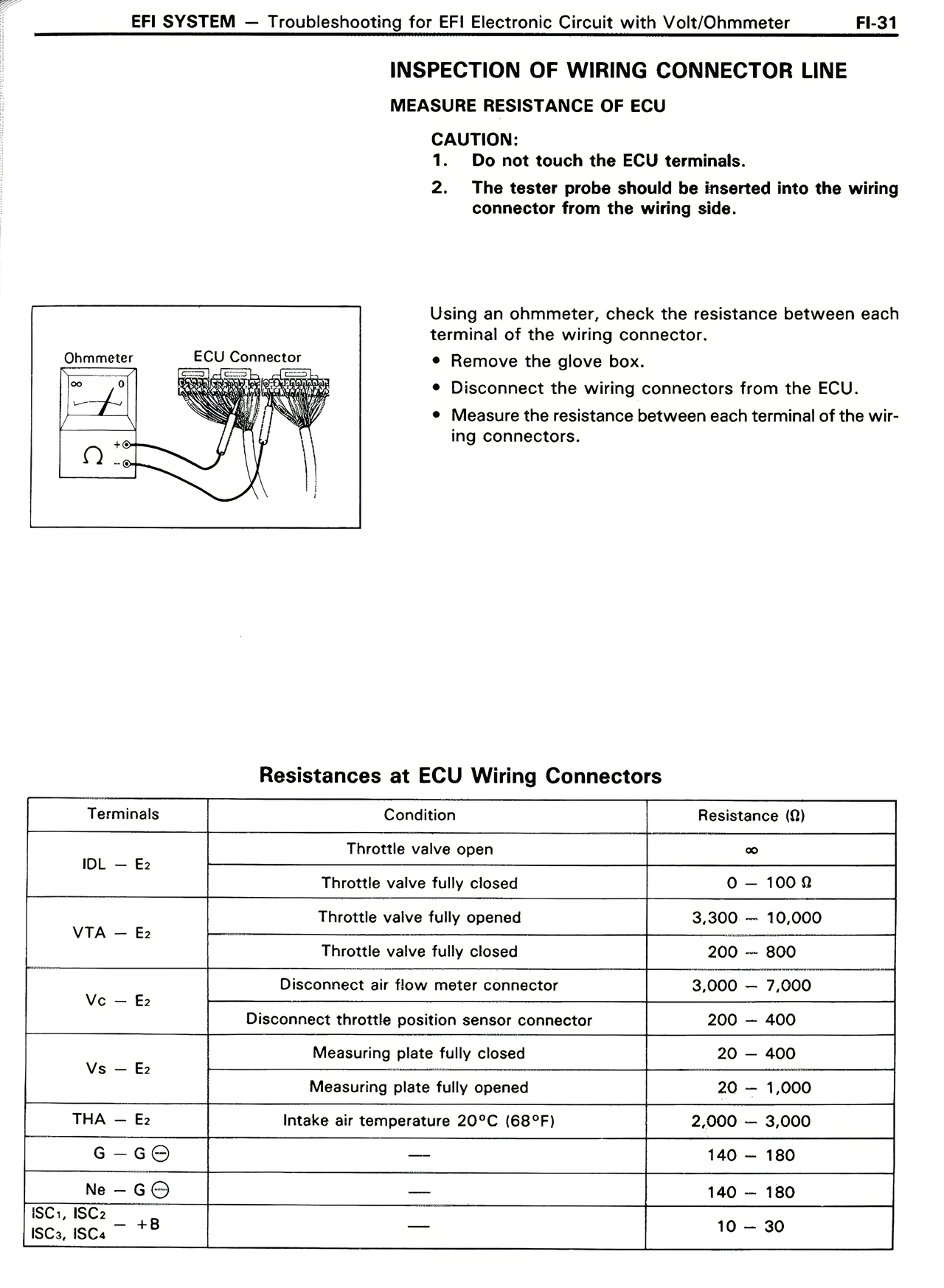
Using an ohmmeter, check the resistance between each terminal of the wiring connector.
• Remove the glove box.
• Disconnect the wiring connectors from the ECU.
• Measure the resistance between each terminal of the wiring connectors.
Resistances at ECU Wiring Connectors
Terminals | Condition | Resistance (Ω)
IDL — E₂ | Throttle valve open | ∞
IDL — E₂ | Throttle valve fully closed | 0 — 100 Ω
VTA — E₂ | Throttle valve fully opened | 3,300 — 10,000
VTA — E₂ | Throttle valve fully closed | 200 — 800
Vc — E₂ | Disconnect air flow meter connector | 3,000 — 7,000
Vc — E₂ | Disconnect throttle position sensor connector | 200 — 400
Vs — E₂ | Measuring plate fully closed | 20 — 400
Vs — E₂ | Measuring plate fully opened | 20 — 1,000
THA — E₂ | Intake air temperature 20°C (68°F) | 2,000 — 3,000
G — G⊖ | — | 140 — 180
Ne — G⊖ | — | 140 — 180
ISC₁, ISC₂ ISC₃, ISC₄ | +B | — | 10 — 30