100%
B HOW TO USE THIS MANUAL
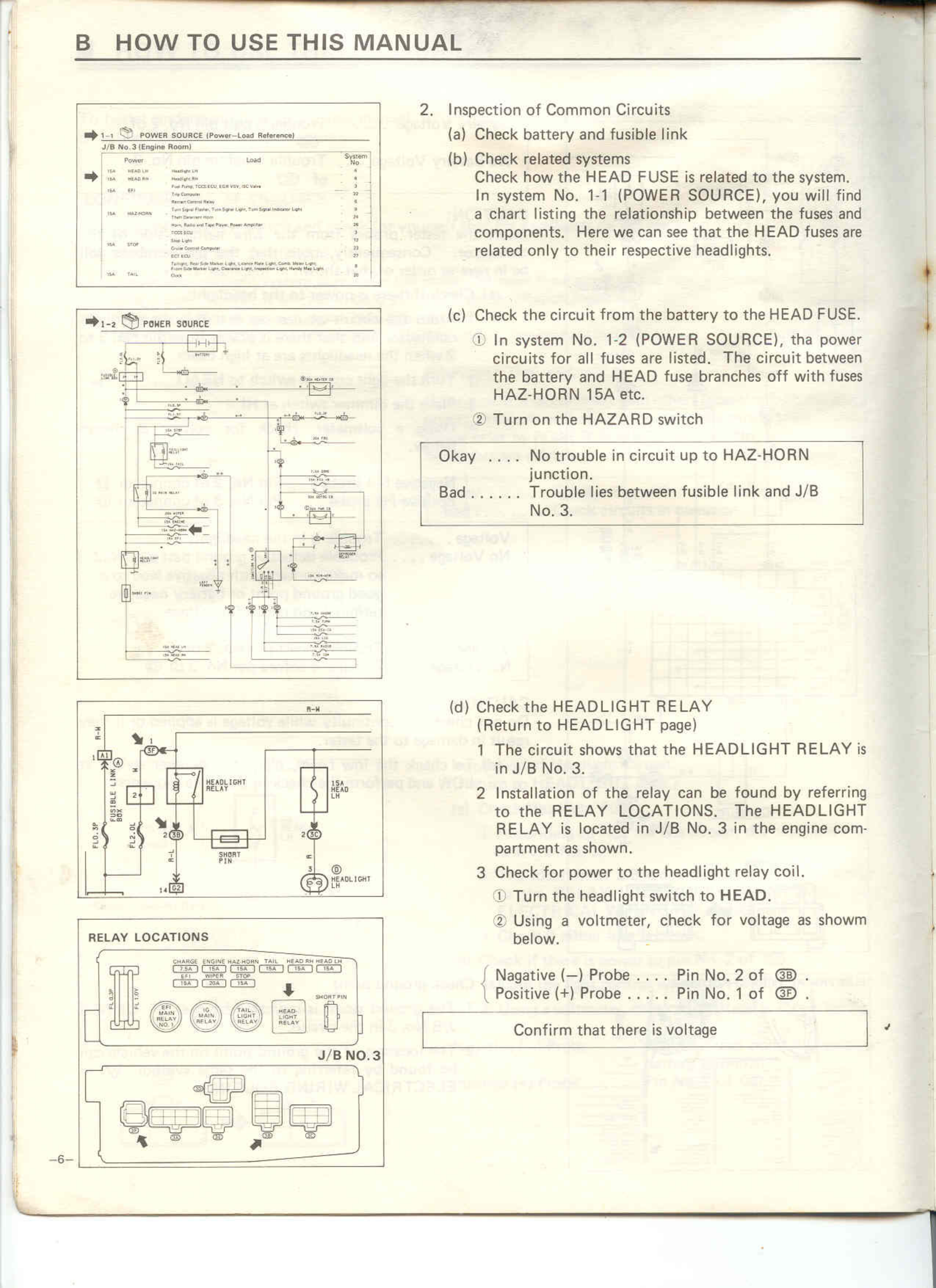
→ 1-1 POWER SOURCE (Power-Load Reference)
J/B No. 3 (Engine Room)
Power Load System No.
HA HEAD-LH Headlight LH 1
HA HEAD-RH Headlight RH 1
Power Circuit Head 2
Headlight Relay 3
HA HORN Horn Horn Relay 3
HORN Fuse 3
Power Circuit Relay 3
HA IGNITION Fuel Signal Valve, Turn Signal Indicator Light, Turn Signal Indicator Light 3
Rear Left 3
HAZ Horn Relay, Fuel Signal Valve, Rear Dimmer 3
DEF FUSE 3
HA STOP Stop Light 3
Stop Light Switch 3
DEF FUSE 3
HA TAIL Dimmer, Headlight LH, Parking Light, License Plate Light, Outline Light 3
Position Light LH, Front Combination Light (RH/LH), Fog Position Light, Parking Light 3
→ 1-2 POWER SOURCE
[Circuit diagram showing electrical connections and components]
RELAY LOCATIONS
[Diagram showing relay locations with labels including CHARGE, IGNITION, MAIN-HORN, TAIL, HEATER, DEFOG and J/B NO.3 junction box layout]
2. Inspection of Common Circuits
(a) Check battery and fusible link
(b) Check related systems
Check how the HEAD FUSE is related to the system.
In system No. 1-1 (POWER SOURCE), you will find
a chart listing the relationship between the fuses and
components. Here we can see that the HEAD fuses are
related only to their respective headlights.
(c) Check the circuit from the battery to the HEAD FUSE.
① In system No. 1-2 (POWER SOURCE), the power
circuits for all fuses are listed. The circuit between
the battery and HEAD fuse branches off with fuses
HAZ-HORN 15A etc.
② Turn on the HAZARD switch
Okay .... No trouble in circuit up to HAZ-HORN
junction.
Bad ...... Trouble lies between fusible link and J/B
No. 3.
(d) Check the HEADLIGHT RELAY
(Return to HEADLIGHT page)
1 The circuit shows that the HEADLIGHT RELAY is
in J/B No. 3.
2 Installation of the relay can be found by referring
to the RELAY LOCATIONS. The HEADLIGHT
RELAY is located in J/B No. 3 in the engine compartment as shown.
3 Check for power to the headlight relay coil.
① Turn the headlight switch to HEAD.
② Using a voltmeter, check for voltage as shown
below.
Negative (-) Probe .... Pin No. 2 of ⓑ .
Positive (+) Probe ..... Pin No. 1 of ⓑ .
Confirm that there is voltage
-6-