100%
15
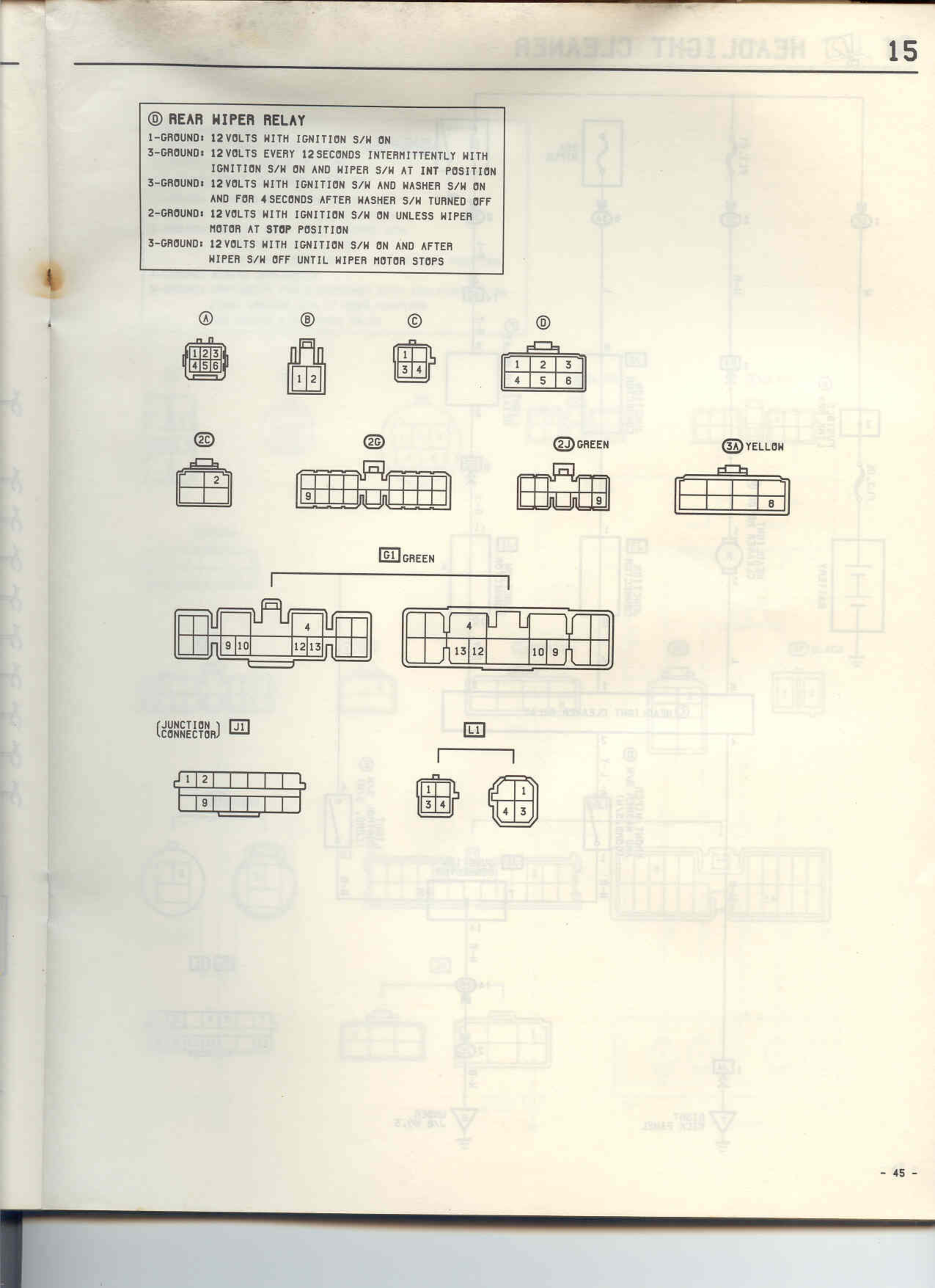
ⓓ REAR WIPER RELAY
1-GROUND: 12 VOLTS WITH IGNITION S/W ON
3-GROUND: 12 VOLTS EVERY 12 SECONDS INTERMITTENTLY WITH IGNITION S/W ON AND WIPER S/W AT INT POSITION
3-GROUND: 12 VOLTS WITH IGNITION S/W AND WASHER S/W ON AND FOR 4 SECONDS AFTER WASHER S/W TURNED OFF
2-GROUND: 12 VOLTS WITH IGNITION S/W ON UNLESS WIPER MOTOR AT STOP POSITION
3-GROUND: 12 VOLTS WITH IGNITION S/W ON AND AFTER WIPER S/W OFF UNTIL WIPER MOTOR STOPS
Ⓐ
[Connector diagram showing pins 1,2,3,4,5,6]
Ⓑ
[Connector diagram showing pins 1,2]
Ⓒ
[Connector diagram showing pins 3,4]
Ⓓ
[Connector diagram showing pins 1,2,3,4,5,6]
20
[Connector diagram showing pins 1,2]
20
[Connector diagram showing multiple pins]
24 GREEN
[Connector diagram showing pins with number 9]
24 YELLOW
[Connector diagram showing pin 8]
D1 GREEN
[Two connector diagrams showing pins 4,9,10,12,13 and 4,13,12,10,9]
(JUNCTION CONNECTOR) J1
[Connector diagram showing pins 1,2,3]
E1
[Two connector diagrams showing pins 3,4 and 1,4,3]
- 45 -