100%
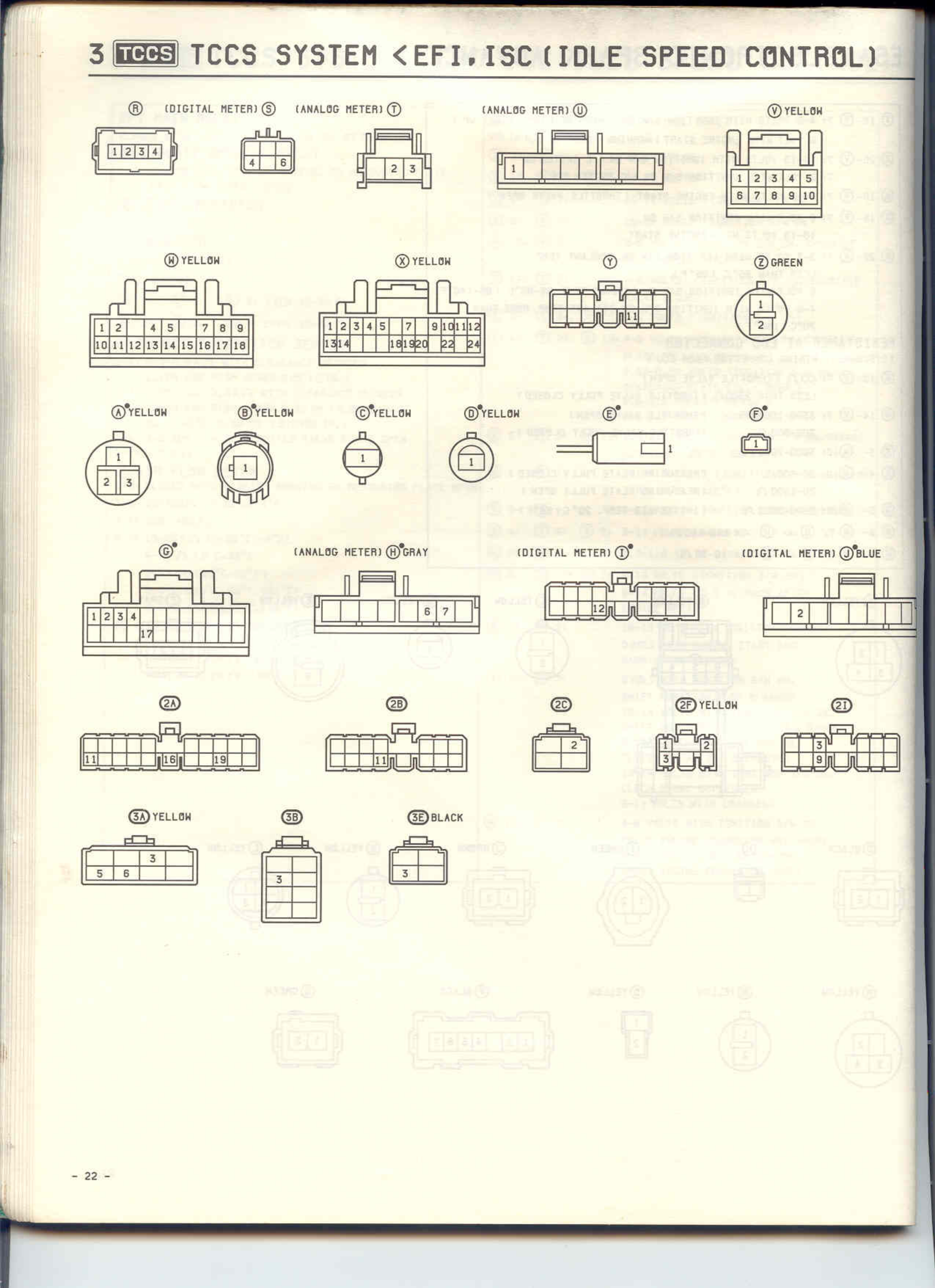
3 TCCS TCCS SYSTEM <EFI.ISC(IDLE SPEED CONTROL)
(DIGITAL METER)⑥ (ANALOG METER)⑦ (ANALOG METER)⑧ ⑨YELLOW
[Connector diagrams showing numbered pins]
⑩YELLOW ⑪YELLOW ⑫ ⑬GREEN
[Connector diagrams with numbered pins 1-18 and other configurations]
⑭YELLOW ⑮YELLOW ⑯YELLOW ⑰YELLOW ⑱* ⑲*
[Various circular and rectangular connector diagrams]
⑳* (ANALOG METER)㉑GRAY (DIGITAL METER)㉒* (DIGITAL METER)㉓BLUE
[Rectangular connector diagrams with numbered positions]
㉔ ㉕ ㉖ ㉗YELLOW ㉘
[Multiple connector diagrams]
㉙YELLOW ㉚ ㉛BLACK
[Final row of connector diagrams with numbered positions]
- 22 -