100%
6
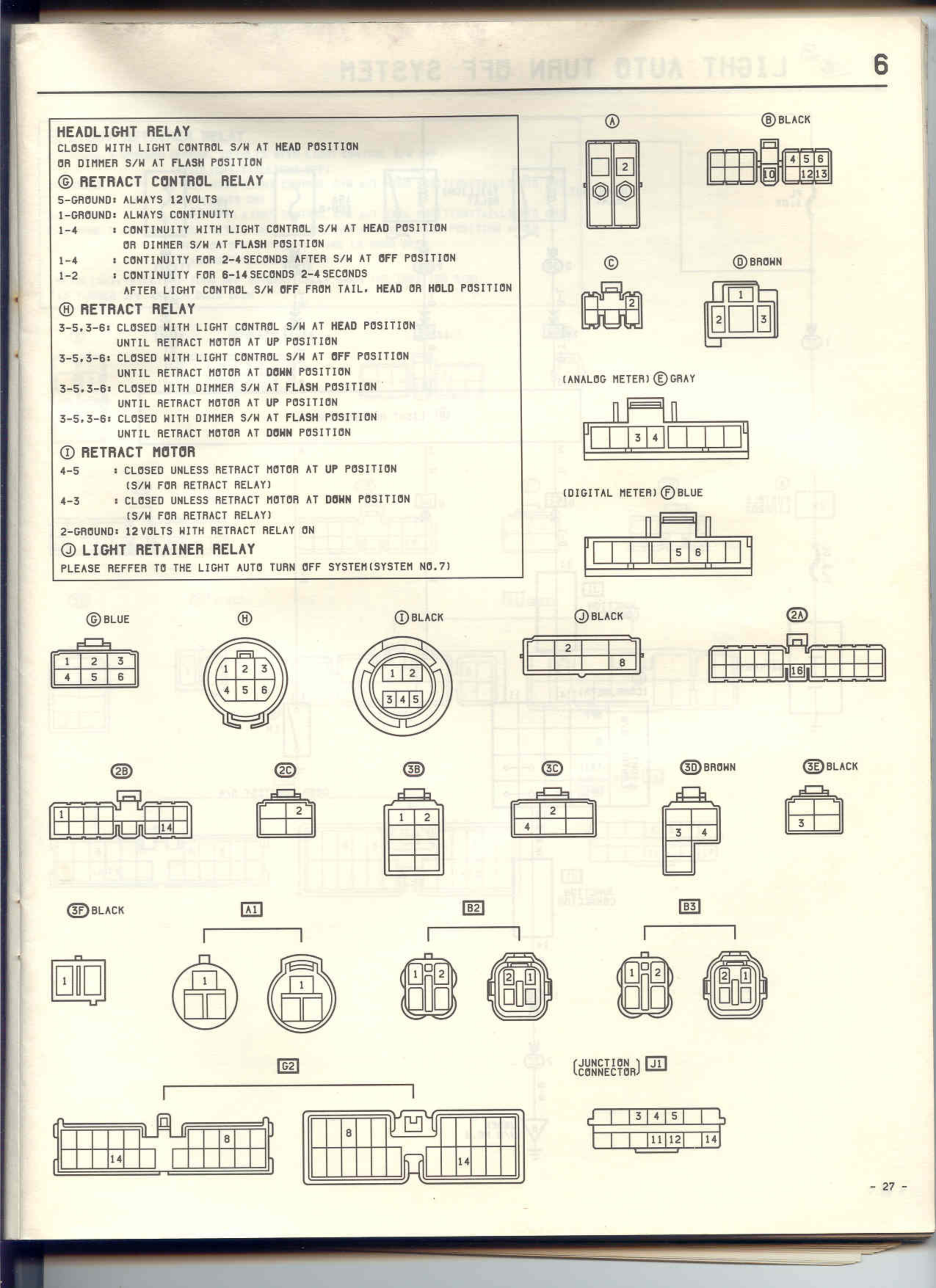
HEADLIGHT RELAY
CLOSED WITH LIGHT CONTROL S/W AT HEAD POSITION
OR DIMMER S/W AT FLASH POSITION
② RETRACT CONTROL RELAY
5-GROUND: ALWAYS 12 VOLTS
1-GROUND: ALWAYS CONTINUITY
1-4 : CONTINUITY WITH LIGHT CONTROL S/W AT HEAD POSITION
OR DIMMER S/W AT FLASH POSITION
1-4 : CONTINUITY FOR 2-4 SECONDS AFTER S/W AT OFF POSITION
1-2 : CONTINUITY FOR 8-14 SECONDS 2-4 SECONDS
AFTER LIGHT CONTROL S/W OFF FROM TAIL- HEAD OR HOLD POSITION
③ RETRACT RELAY
3-5,3-6: CLOSED WITH LIGHT CONTROL S/W AT HEAD POSITION
UNTIL RETRACT MOTOR AT UP POSITION
3-5,3-6: CLOSED WITH LIGHT CONTROL S/W AT OFF POSITION
UNTIL RETRACT MOTOR AT DOWN POSITION
3-5,3-6: CLOSED WITH DIMMER S/W AT FLASH POSITION
UNTIL RETRACT MOTOR AT UP POSITION
3-5,3-6: CLOSED WITH DIMMER S/W AT FLASH POSITION
UNTIL RETRACT MOTOR AT DOWN POSITION
④ RETRACT MOTOR
4-3 : CLOSED UNLESS RETRACT MOTOR AT UP POSITION
(S/W FOR RETRACT RELAY)
4-3 : CLOSED UNLESS RETRACT MOTOR AT DOWN POSITION
(S/W FOR RETRACT RELAY)
2-GROUND: 12 VOLTS WITH RETRACT RELAY ON
⑤ LIGHT RETAINER RELAY
PLEASE REFFER TO THE LIGHT AUTO TURN OFF SYSTEM(SYSTEM NO.7)
① [Diagram showing 2-pin connector with pins 1, 2]
② BLACK [Diagram showing 6-pin connector with pins arranged 4,5,6 top row, U,1,2,3 bottom row]
③ [Diagram showing 3-pin connector arranged in triangular pattern with pins 1,2,3]
④ BROWN [Diagram showing 3-pin connector with pins 1,2,3]
(ANALOG METER) ⑤ GRAY [Diagram showing 6-pin connector in rectangular housing with pins 3,4 visible]
(DIGITAL METER) ⑥ BLUE [Diagram showing 7-pin connector in rectangular housing with pins 5,6 visible]
⑦ BLUE [Diagram showing 6-pin connector arranged in 2 rows: 1,2,3 top, 4,5,6 bottom]
⑧ [Diagram showing circular 5-pin connector with pins 1,2,3,4,5]
⑨ BLACK [Diagram showing circular 5-pin connector with pins 1,2,3,4,5]
⑩ BLACK [Diagram showing 2-pin connector with pins 2,8]
21 [Diagram showing 12-pin connector with U pin visible]
2B [Diagram showing 6-pin connector]
2C [Diagram showing 2-pin connector with pins 1,2]
3B [Diagram showing 2-pin connector with pins 1,2]
3C [Diagram showing 3-pin connector with pins 4,2,1]
3D BROWN [Diagram showing 2-pin connector with pins 3,4]
3E BLACK [Diagram showing 2-pin connector with pin 3]
3F BLACK [Diagram showing single pin connector]
A1 [Diagram showing two circular connectors, each with single pin labeled 1]
B2 [Diagram showing two circular 2-pin connectors with pins 1,2 each]
B3 [Diagram showing two circular 2-pin connectors with pins 1,2 each]
D2 [Diagram showing two large multi-pin connectors with pins 8,14 visible]
(JUNCTION BOX CONNECTOR) J1 [Diagram showing rectangular connector with pins 3,4,5 top row and 11,12,13,14 bottom row]
- 27 -