100%
5. INSTALL TWELVE PISTON RETURN SPRINGS AND SET RETAINER WITH SNAP RING IN PLACE
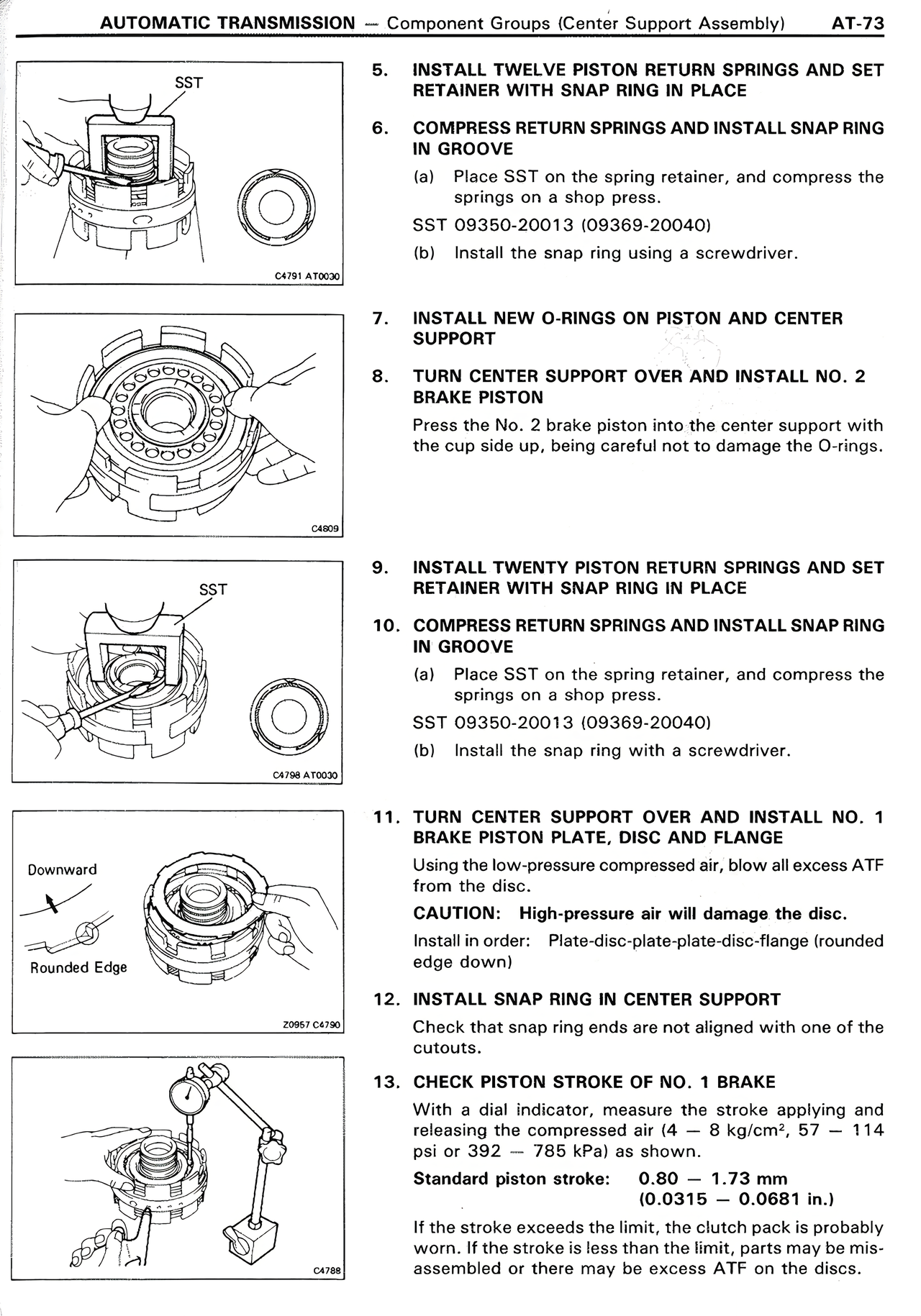
6. COMPRESS RETURN SPRINGS AND INSTALL SNAP RING IN GROOVE
(a) Place SST on the spring retainer, and compress the springs on a shop press.
SST 09350-20013 (09369-20040)
(b) Install the snap ring using a screwdriver.
7. INSTALL NEW O-RINGS ON PISTON AND CENTER SUPPORT
8. TURN CENTER SUPPORT OVER AND INSTALL NO. 2 BRAKE PISTON
Press the No. 2 brake piston into the center support with the cup side up, being careful not to damage the O-rings.
9. INSTALL TWENTY PISTON RETURN SPRINGS AND SET RETAINER WITH SNAP RING IN PLACE
10. COMPRESS RETURN SPRINGS AND INSTALL SNAP RING IN GROOVE
(a) Place SST on the spring retainer, and compress the springs on a shop press.
SST 09350-20013 (09369-20040)
(b) Install the snap ring with a screwdriver.
11. TURN CENTER SUPPORT OVER AND INSTALL NO. 1 BRAKE PISTON PLATE, DISC AND FLANGE
Using the low-pressure compressed air, blow all excess ATF from the disc.
CAUTION: High-pressure air will damage the disc.
Install in order: Plate-disc-plate-plate-disc-flange (rounded edge down)
12. INSTALL SNAP RING IN CENTER SUPPORT
Check that snap ring ends are not aligned with one of the cutouts.
13. CHECK PISTON STROKE OF NO. 1 BRAKE
With a dial indicator, measure the stroke applying and releasing the compressed air (4 — 8 kg/cm²; 57 — 114 psi or 392 — 785 kPa) as shown.
Standard piston stroke: 0.80 — 1.73 mm (0.0315 — 0.0681 in.)
If the stroke exceeds the limit, the clutch pack is probably worn. If the stroke is less than the limit, parts may be mis-assembled or there may be excess ATF on the discs.