100%
BE-14 BODY ELECTRICAL SYSTEM — Lighting
(f) Place the ball on the spring, position the lever at HI, and install the plate.
(g) Insure that the switch operates smoothly.
(h) Connect the terminals to the connector. (See pages BE-3 and 13)
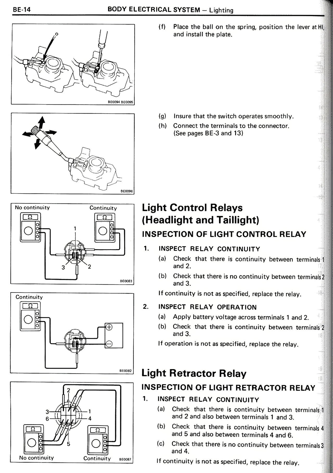
Light Control Relays
(Headlight and Taillight)
INSPECTION OF LIGHT CONTROL RELAY
1. INSPECT RELAY CONTINUITY
(a) Check that there is continuity between terminals 1 and 2.
(b) Check that there is no continuity between terminals 2 and 3.
If continuity is not as specified, replace the relay.
2. INSPECT RELAY OPERATION
(a) Apply battery voltage across terminals 1 and 2.
(b) Check that there is continuity between terminals 2 and 3.
If operation is not as specified, replace the relay.
Light Retractor Relay
INSPECTION OF LIGHT RETRACTOR RELAY
1. INSPECT RELAY CONTINUITY
(a) Check that there is continuity between terminals 1 and 2 and also between terminals 4 and 6.
(b) Check that there is continuity between terminals 4 and 5 and also between terminals 4 and 6.
(c) Check that there is no continuity between terminals 3 and 4.
If continuity is not as specified, replace the relay.