100%
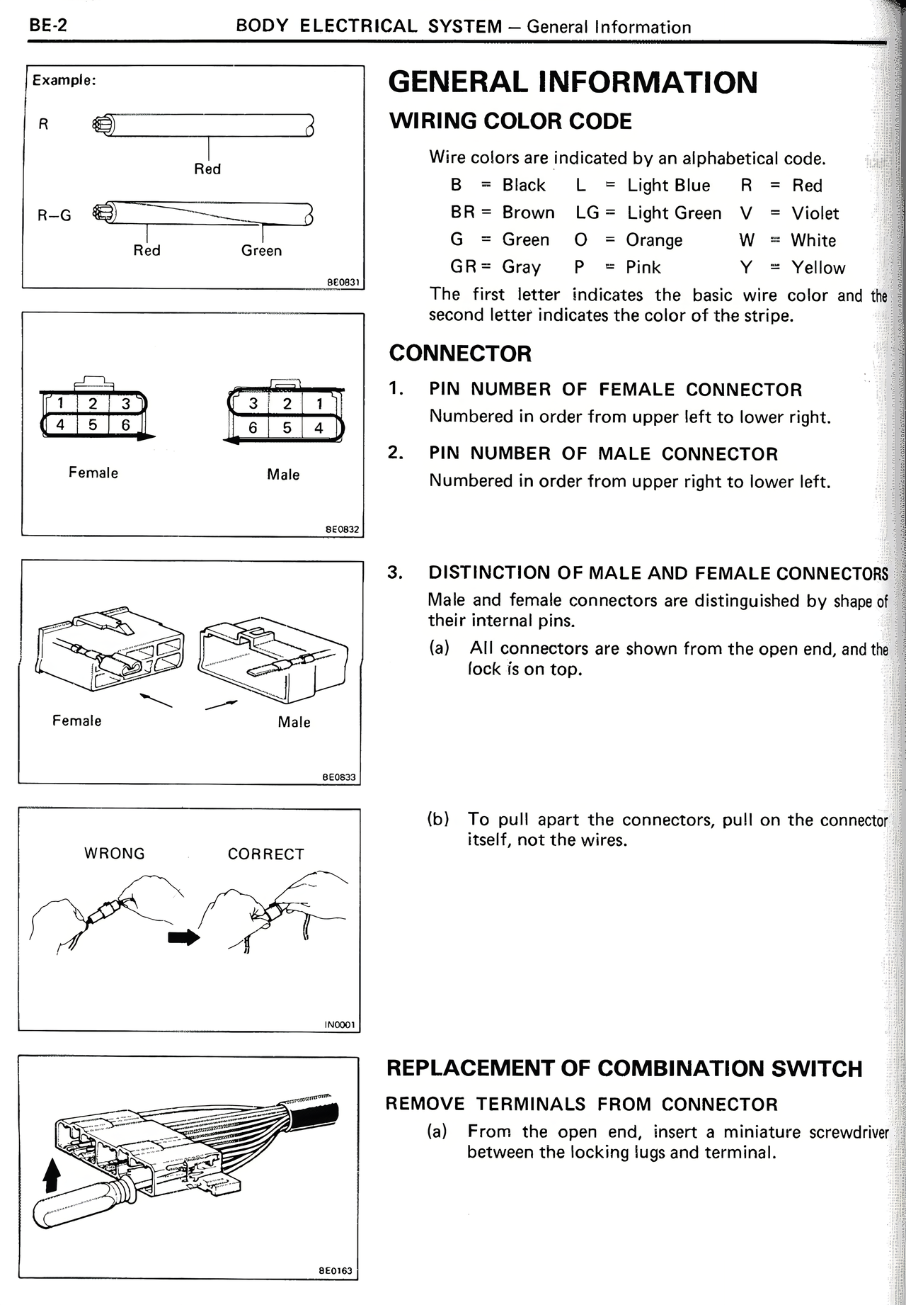
Example:
R
Red
R-G
Red Green
BE0831
Female Male
BE0832
Female Male
BE0833
WRONG CORRECT
BE0001
BE0043
GENERAL INFORMATION
WIRING COLOR CODE
Wire colors are indicated by an alphabetical code.
B = Black L = Light Blue R = Red
BR = Brown LG = Light Green V = Violet
G = Green O = Orange W = White
GR = Gray P = Pink Y = Yellow
The first letter indicates the basic wire color and the second letter indicates the color of the stripe.
CONNECTOR
1. PIN NUMBER OF FEMALE CONNECTOR
Numbered in order from upper left to lower right.
2. PIN NUMBER OF MALE CONNECTOR
Numbered in order from upper right to lower left.
3. DISTINCTION OF MALE AND FEMALE CONNECTORS
Male and female connectors are distinguished by shape of their internal pins.
(a) All connectors are shown from the open end, and the lock is on top.
(b) To pull apart the connectors, pull on the connector itself, not the wires.
REPLACEMENT OF COMBINATION SWITCH
REMOVE TERMINALS FROM CONNECTOR
(a) From the open end, insert a miniature screwdriver between the locking lugs and terminal.