← p.022p.024 →
BE/Body Electrical System — Replacement of Front Wiper and Washer Switch, page 23
23 / 121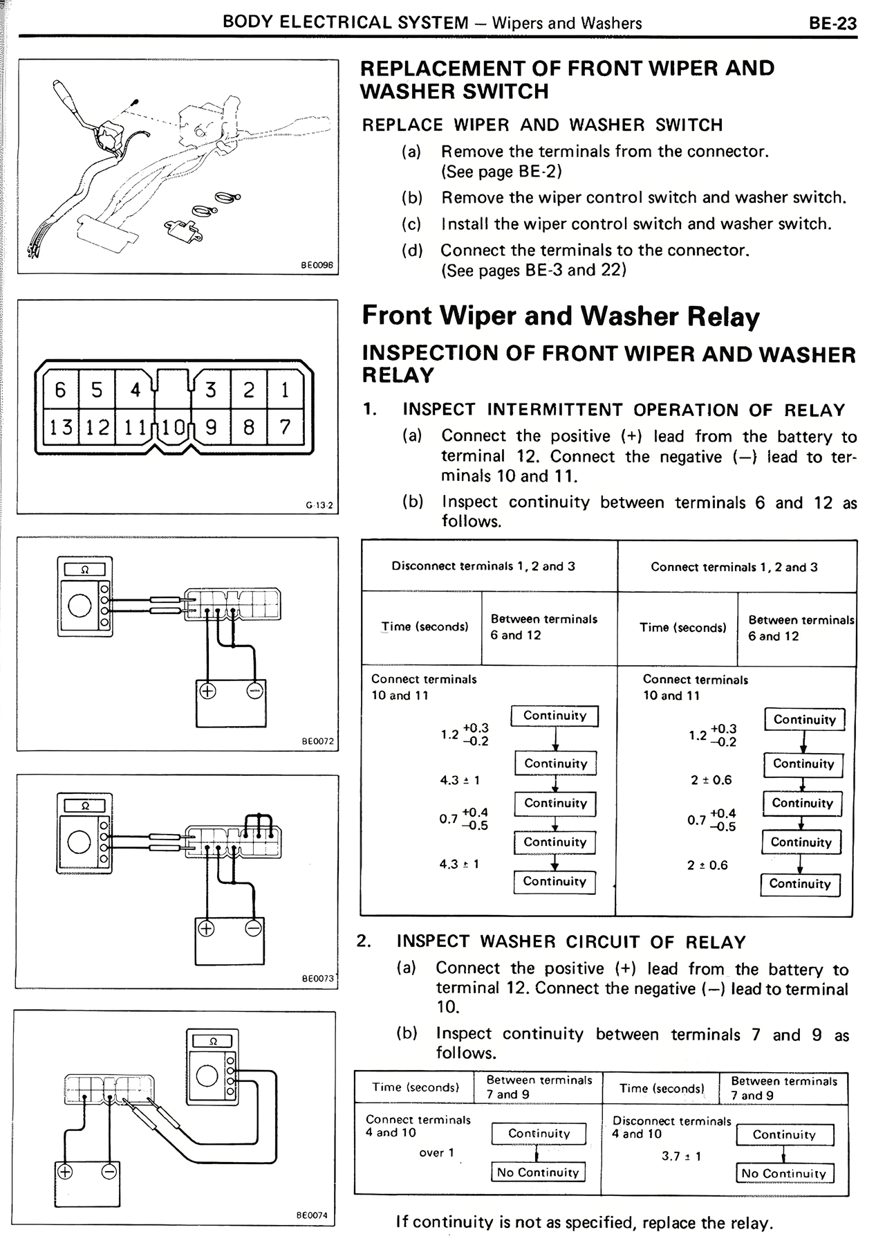
100%
Page text (OCR transcript)
REPLACEMENT OF FRONT WIPER AND
WASHER SWITCH

REPLACE WIPER AND WASHER SWITCH
(a) Remove the terminals from the connector.
(See page BE 2)
(b) Remove the wiper control switch and washer switch.
(c) Install the wiper control switch and washer switch.
(d) Connect the terminals to the connector.
(See pages BE 3 and 22)

Front Wiper and Washer Relay

INSPECTION OF FRONT WIPER AND WASHER
RELAY

1. INSPECT INTERMITTENT OPERATION OF RELAY
(a) Connect the positive (+) lead from the battery to
terminal 12. Connect the negative (-) lead to ter-
minals 10 and 11.
(b) Inspect continuity between terminals 6 and 12 as
follows.

Disconnect terminals 1, 2 and 3

Time (seconds) | Between terminals 6 and 12

Connect terminals
10 and 11
1.2 +10.3 -0.2 | Continuity
4.3 ± 1 | Continuity
0.7 +0.4 -0.5 | Continuity
4.3 ± 1 | Continuity

Connect terminals 1, 2 and 3

Time (seconds) | Between terminals 6 and 12

Connect terminals
10 and 11
1.2 +10.3 -0.2 | Continuity
2 ± 0.6 | Continuity
0.7 +0.4 -0.5 | Continuity
2 ± 0.6 | Continuity

2. INSPECT WASHER CIRCUIT OF RELAY
(a) Connect the positive (+) lead from the battery to
terminal 12. Connect the negative (-) lead to terminal
10.
(b) Inspect continuity between terminals 7 and 9 as
follows.

Time (seconds) | Between terminals 7 and 9 | Time (seconds) | Between terminals 7 and 9

Disconnect terminals
4 and 10
over 1 | Continuity | 3.7 ± 1 | No Continuity

If continuity is not as specified, replace the relay.