100%
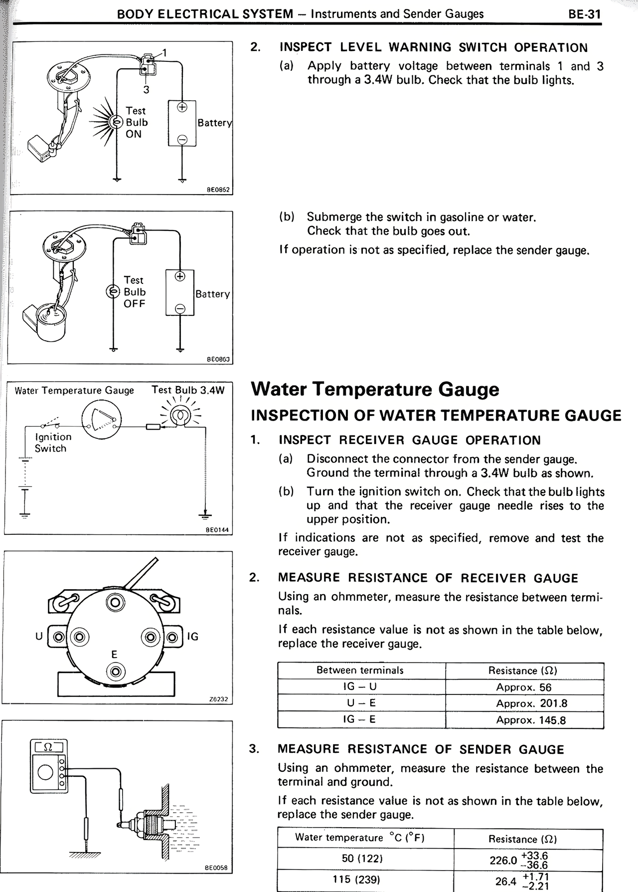
2. INSPECT LEVEL WARNING SWITCH OPERATION
(a) Apply battery voltage between terminals 1 and 3 through a 3.4W bulb. Check that the bulb lights.
(b) Submerge the switch in gasoline or water. Check that the bulb goes out.
If operation is not as specified, replace the sender gauge.
Water Temperature Gauge
INSPECTION OF WATER TEMPERATURE GAUGE
1. INSPECT RECEIVER GAUGE OPERATION
(a) Disconnect the connector from the sender gauge. Ground the terminal through a 3.4W bulb as shown.
(b) Turn the ignition switch on. Check that the bulb lights up and that the receiver gauge needle rises to the upper position.
If indications are not as specified, remove and test the receiver gauge.
2. MEASURE RESISTANCE OF RECEIVER GAUGE
Using an ohmmeter, measure the resistance between terminals.
If each resistance value is not as shown in the table below, replace the receiver gauge.
Between terminals | Resistance (Ω)
IG-U | Approx. 56
U-E | Approx. 201.8
IG-E | Approx. 145.8
3. MEASURE RESISTANCE OF SENDER GAUGE
Using an ohmmeter, measure the resistance between the terminal and ground.
If each resistance value is not as shown in the table below, replace the sender gauge.
Water temperature °C (°F) | Resistance (Ω)
50 (122) | 226.0 +33.9/-24.8
115 (239) | 26.4 +4.0/-2.8