100%
BE-36
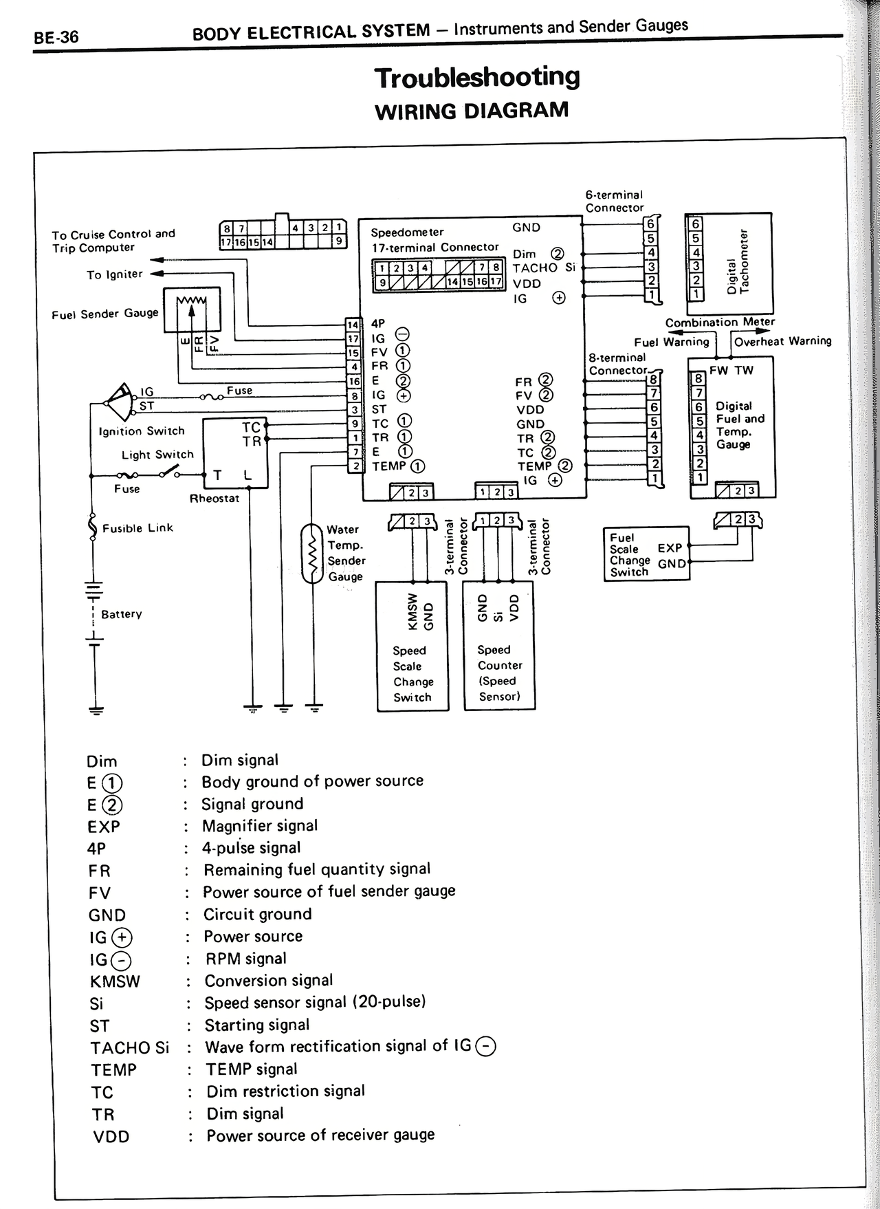
BODY ELECTRICAL SYSTEM — Instruments and Sender Gauges
Troubleshooting
WIRING DIAGRAM
To Cruise Control and
ECT Computer
To Igniter
Fuel Sender Gauge
Ignition Switch
Light Switch
Fusible Link
Battery
G-terminal
(5-terminal)
Speedometer
17-terminal Connector
Dim
E①
E②
FV
FR
IG
SI
ST
TR
E
TEMP①
Water
Temp.
Sender
Gauge
Speed
Scale
Change
Switch
Speed
Counter
(Speed
Sensor)
FB ②
FV ②
VDD
GND
TC ②
TEMP ②
8-terminal
Connector
Combination Meter
Fuel Warning
Digi-heat Warning
Digital
Fuel and
Temp.
Gauge
Fuel
Scale
Change
Switch
EXP
GND
Dim : Dim signal
E ① : Body ground of power source
E ② : Signal ground
EXP : Magnifier signal
4P : 4-pulse signal
FR : Remaining fuel quantity signal
FV : Power source of fuel sender gauge
GND : Circuit ground
IG① : Power source
IG② : RPM signal
KMSW : Conversion signal
SI : Speed sensor signal (20-pulse)
ST : Starting signal
TACHO SI : Wave form rectification signal of IG②
TEMP : TEMP signal
TC : Dim restriction signal
TR : Dim signal
VDD : Power source of receiver gauge