100%
ON-VEHICLE INSPECTION OF COMBINATION
METER (Digital Type)
1. REMOVE COMBINATION METER AND CONNECT
SUB-HARNESS (SST)
SST 09082-00100
2. INSPECT CIRCUIT AND PARTS OPERATION
Terminals of
sub-harness Specification
E(1)—Body ground Continuity Zero Ω
E(2)—Body ground
IG(⊖)—E(1) Battery voltage (Ignition switch ON)
ST — E(1) 8 — 11V (Cranking)
TC — E(1) Battery voltage (Light switch and rheostat turned ON.)
0 V (Light switch turned ON and rheostat turned OFF.)
TR — E(1) 0 — 1.0V (Light switch turned OFF.)
0 — 1.0V (Light switch turned ON and rheostat MIN)
6 — 9V (Light switch turned ON and rheostat MAX)
4P — E(1) [WAVEFORM DIAGRAM: about 10V / about 0V]
4 times/revolution of magnet shaft (Ignition switch ON)
FV — E(2) 4.0 — 6.0V (Ignition switch ON)
FR — E(2) 4.4 — 4.8V (F level) (Ignition switch ON)
3.27V (1/2 level) (Ignition switch ON)
2.3 — 2.7V (1/4 level) (Ignition switch ON)
0.3 — 0.5V (E level) (Ignition switch ON)
IG(⊖)— E(1) 11 — 13V (Idling)
10 — 12V (3,000 rpm)
TEMP — E(2) 1.7V (No. 6 segment is lighted) (Ignition switch ON)
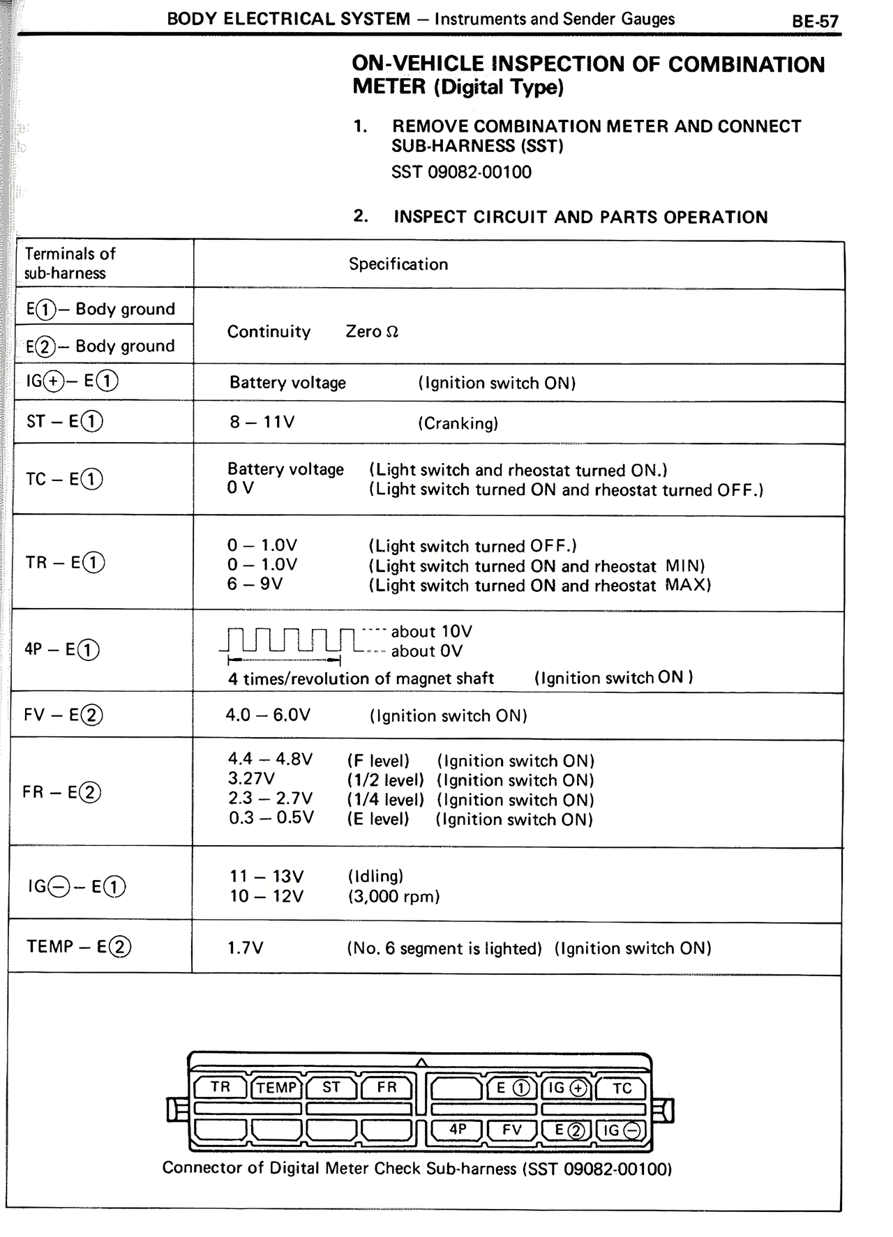
[DIAGRAM: Connector layout showing terminals TR, TEMP, ST, FR, with lower row showing terminals 4P, FV, E(2), IG(⊖), TC, E(1)]
Connector of Digital Meter Check Sub-harness (SST 09082-00100)