100%
FUEL EVAPORATIVE EMISSION CONTROL (EVAP) SYSTEM
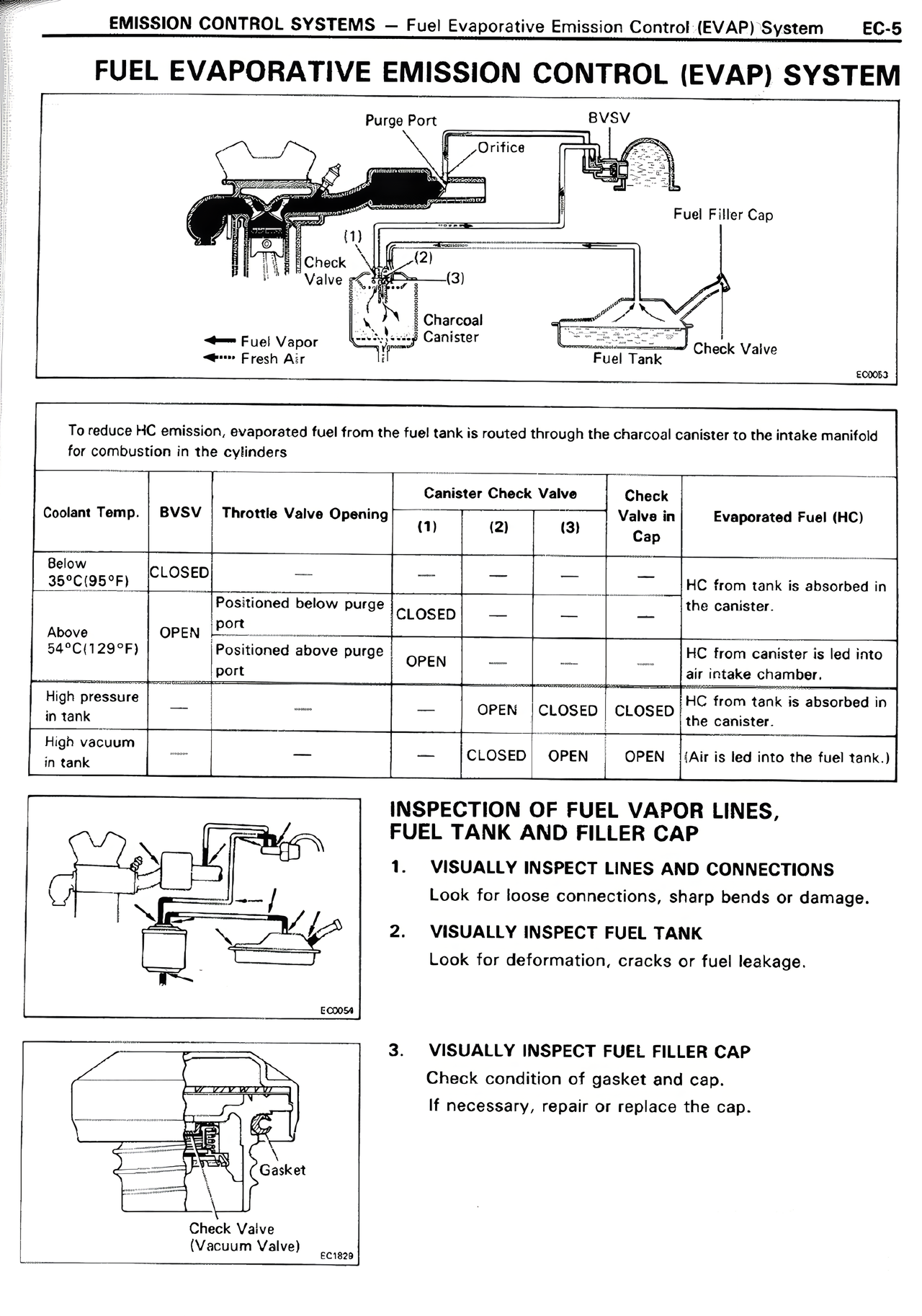
[Diagram showing EVAP system with labeled components: Purge Port, BVSV, Orifice, Fuel Filler Cap, Check Valve (1), Check Valve (2), Check Valve (3), Charcoal Canister, Fuel Tank, Check Valve, with arrows indicating Fuel Vapor and Fresh Air flow]
To reduce HC emission, evaporated fuel from the fuel tank is routed through the charcoal canister to the intake manifold for combustion in the cylinders
[TABLE:
Coolant Temp. | BVSV | Throttle Valve Opening | Canister Check Valve (1) (2) (3) | Check Valve in Cap | Evaporated Fuel (HC)
Below 50°C(122°F) | CLOSED | — | — | — | — | — | HC from tank is absorbed in the canister.
Above 54°C(129°F) | OPEN | Positioned below purge port | CLOSED | — | — | — | HC from tank is absorbed in the canister.
| | | Positioned above purge port | OPEN | — | — | — | HC from canister is led into air intake chamber.
High pressure in tank | — | — | — | OPEN | CLOSED | CLOSED | HC from tank is absorbed in the canister.
High vacuum in tank | — | — | — | — | OPEN | OPEN | (Air is led into the fuel tank.)]
INSPECTION OF FUEL VAPOR LINES, FUEL TANK AND FILLER CAP
1. VISUALLY INSPECT LINES AND CONNECTIONS
Look for loose connections, sharp bends or damage.
2. VISUALLY INSPECT FUEL TANK
Look for deformation, cracks or fuel leakage.
3. VISUALLY INSPECT FUEL FILLER CAP
Check condition of gasket and cap.
If necessary, repair or replace the cap.
[Diagrams showing fuel vapor line connections and filler cap with gasket and check valve (vacuum valve)]