100%
ASSEMBLY OF PISTON AND CONNECTING ROD ASSEMBLY
1. ASSEMBLE PISTON AND CONNECTING ROD
(a) Install a new snap ring on one side of the piston pin hole.
(b) Heat the piston in hot water to approx. 60°C (140°F).
(c) Align the notch on the piston with the mark on the rod and push the piston pin in with your thumb.
(d) Install a new snap ring on the other side of the pin.
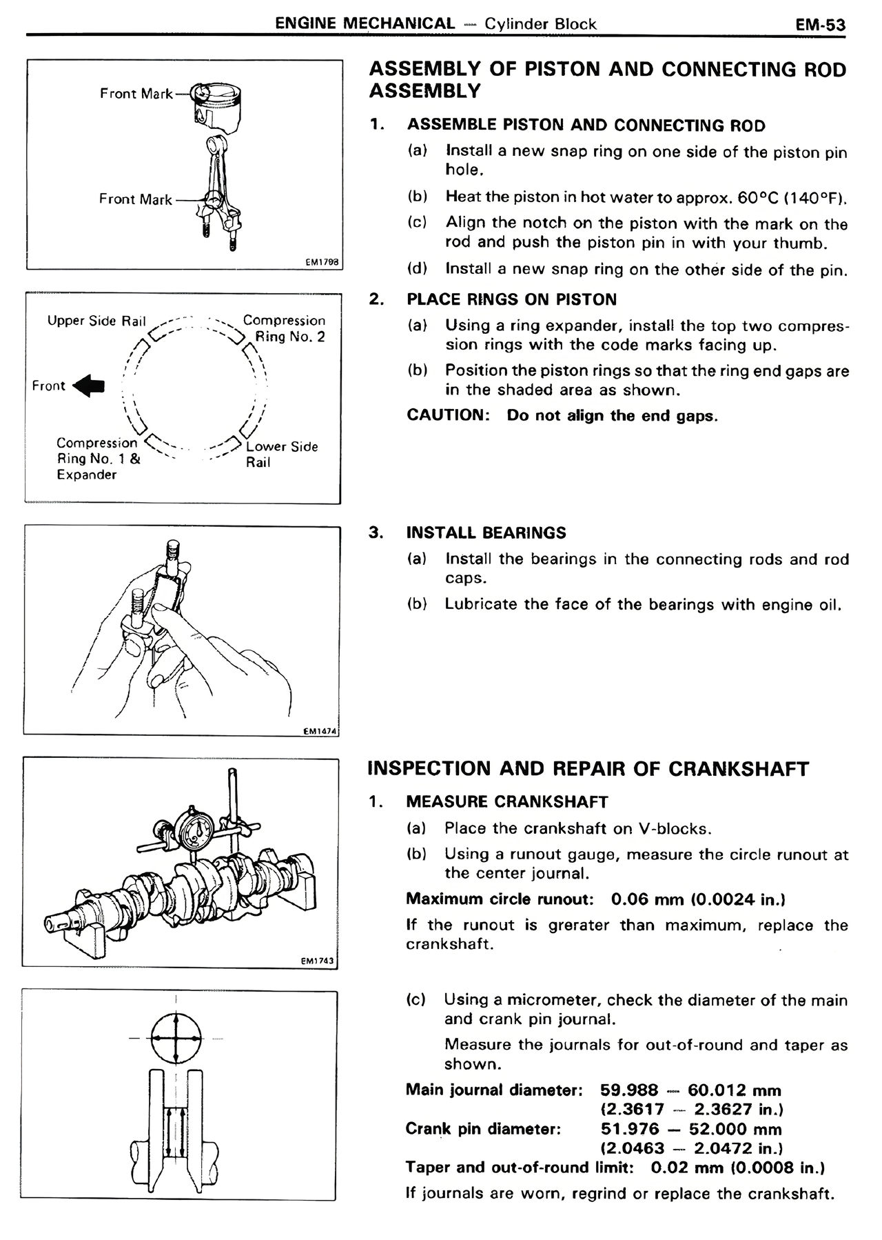
2. PLACE RINGS ON PISTON
(a) Using a ring expander, install the top two compression rings with the code marks facing up.
(b) Position the piston rings so that the ring end gaps are in the shaded area as shown.
CAUTION: Do not align the end gaps.
3. INSTALL BEARINGS
(a) Install the bearings in the connecting rods and rod caps.
(b) Lubricate the face of the bearings with engine oil.
INSPECTION AND REPAIR OF CRANKSHAFT
1. MEASURE CRANKSHAFT
(a) Place the crankshaft on V-blocks.
(b) Using a runout gauge, measure the circle runout at the center journal.
Maximum circle runout: 0.06 mm (0.0024 in.)
If the runout is greater than maximum, replace the crankshaft.
(c) Using a micrometer, check the diameter of the main and crank pin journal.
Measure the journals for out-of-round and taper as shown.
Main journal diameter: 59.988 — 60.012 mm
(2.3617 — 2.3627 in.)
Crank pin diameter: 51.976 — 52.000 mm
(2.0463 — 2.0472 in.)
Taper and out-of-round limit: 0.02 mm (0.0008 in.)
If journals are worn, regrind or replace the crankshaft.
Front Mark
Front Mark
EM1798
Upper Side Rail
Compression Ring No. 2
Front
Compression Ring No. 1 & Expander
Lower Side Rail
EM1412
EM1751