100%
EFI SYSTEM — Troubleshooting for EFI Electronic Circuit with Volt/Ohmmeter FI-43
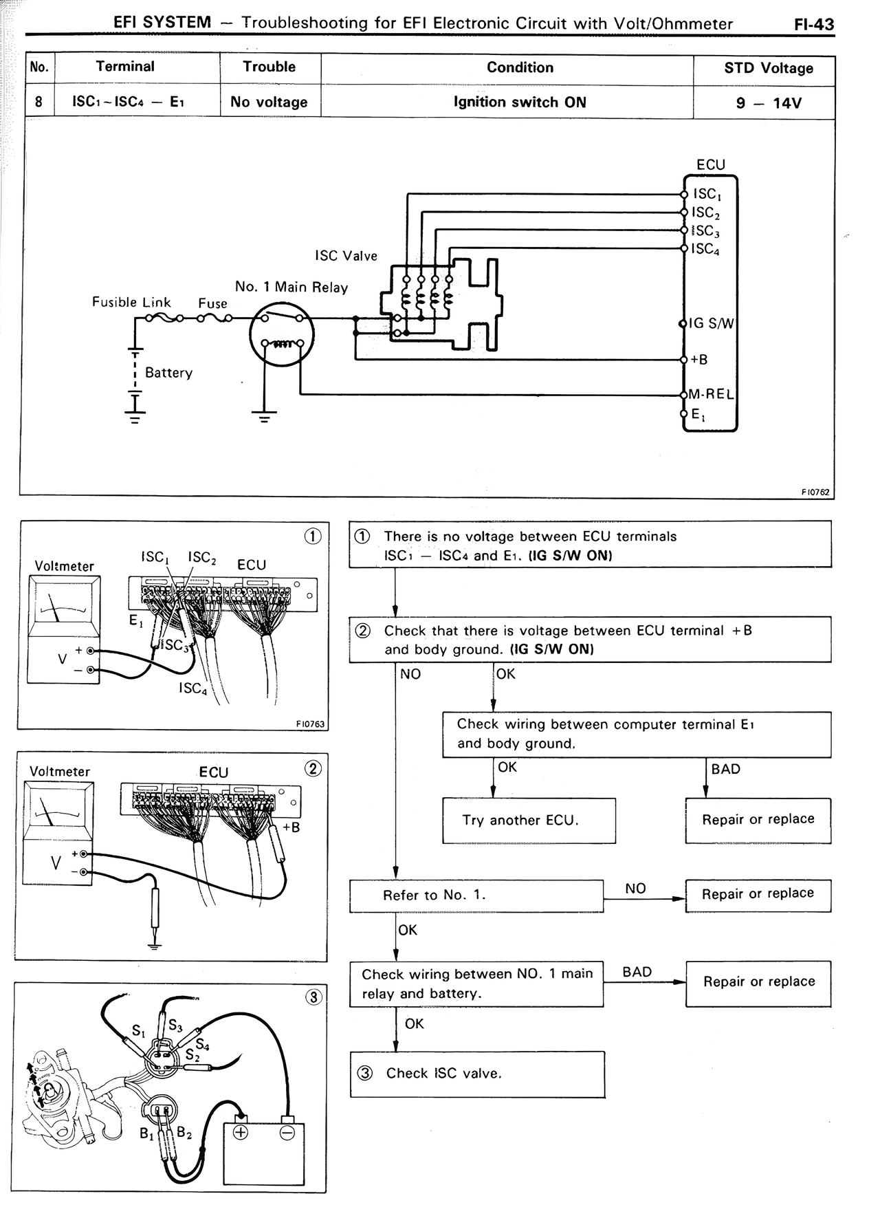
No. Terminal Trouble Condition STD Voltage
8 ISC₁ – ISC₄ — E₁ No voltage Ignition switch ON 9 — 14V
[CIRCUIT DIAGRAM showing Battery, Fusible Link, Fuse, No. 1 Main Relay, ISC Valve, ECU with terminals ISC₁, ISC₂, ISC₃, ISC₄, +IG S/W, +B, M-REL, E₁]
[DIAGRAM 1]
Voltmeter connected between ISC₁ (ECU) and E₁, showing ISC₂, ISC₃, ISC₄
FI070
① There is no voltage between ECU terminals ISC₁ — ISC₄ and E₁. (IG S/W ON)
[DIAGRAM 2]
Voltmeter connected to ECU terminal +B
FI076
② Check that there is voltage between ECU terminal +B and body ground. (IG S/W ON)
NO OK
↓ ↓
Check wiring between computer terminal E₁ and body ground.
OK BAD
↓ ↓
Try another ECU. Repair or replace
↓
Refer to No. 1. NO → Repair or replace
OK
↓
Check wiring between NO. 1 main relay and battery. BAD → Repair or replace
OK
↓
③ Check ISC valve.
[DIAGRAM 3]
Drawing of ISC valve showing terminals S₁, S₂, S₃, S₄, B₁, B₂ connected to battery
FI077