100%
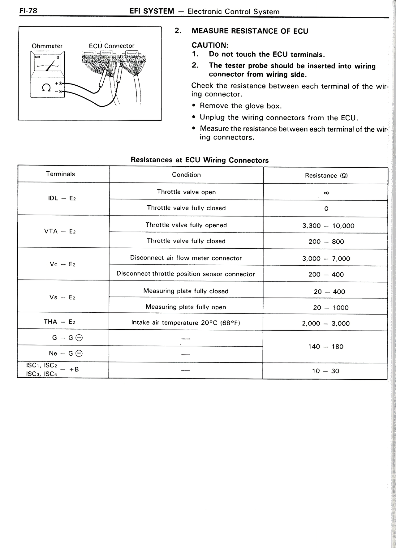
2. MEASURE RESISTANCE OF ECU
CAUTION:
1. Do not touch the ECU terminals.
2. The tester probe should be inserted into wiring connector from wiring side.
Check the resistance between each terminal of the wiring connector.
• Remove the glove box.
• Unplug the wiring connectors from the ECU.
• Measure the resistance between each terminal of the wiring connectors.
Resistances at ECU Wiring Connectors
Terminals | Condition | Resistance (Ω)
IDL — E₂ | Throttle valve open | ∞
IDL — E₂ | Throttle valve fully closed | 0
VTA — E₂ | Throttle valve fully opened | 3,300 — 10,000
VTA — E₂ | Throttle valve fully closed | 200 — 800
Vc — E₂ | Disconnect air flow meter connector | 3,000 — 7,000
Vc — E₂ | Disconnect throttle position sensor connector | 200 — 400
Vs — E₂ | Measuring plate fully closed | 20 — 400
Vs — E₂ | Measuring plate fully open | 20 — 1000
THA — E₂ | Intake air temperature 20°C (68°F) | 2,000 — 3,000
G — G⊖ | — | 140 — 180
Ne — G⊖ | — | —
ISC₁, ISC₂ — +B | — | 10 — 30
ISC₃, ISC₄