AC-38
AIR CONDITIONING SYSTEM — A/C Control Panel Assembly
A/C CONTROL PANEL ASSEMBLY
INSPECTION OF A/C CONTROL PANEL
ASSEMBLY
1. REMOVE A/C CONTROL PANEL ASSEMBLY
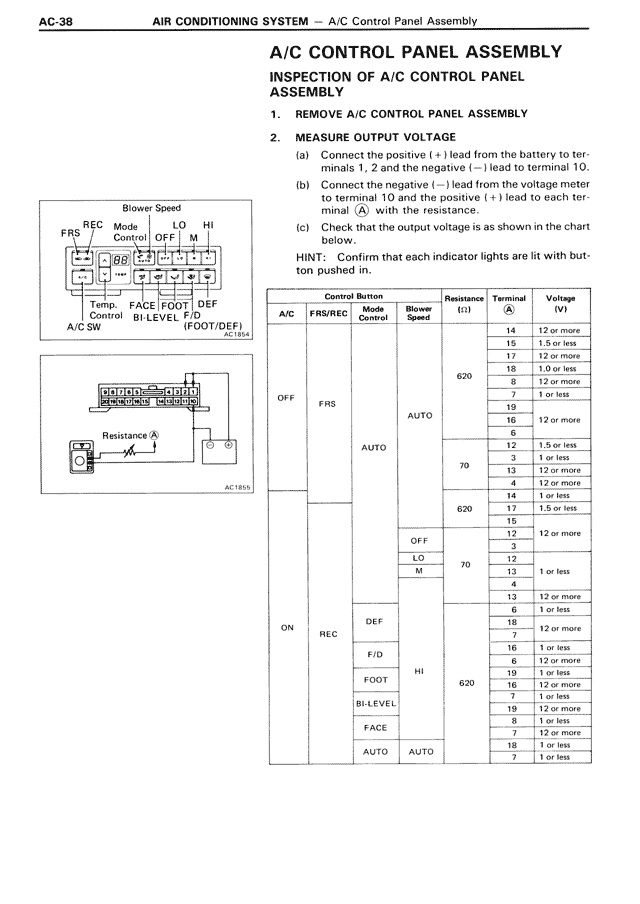
2. MEASURE OUTPUT VOLTAGE
(a) Connect the positive (+) lead from the battery to terminals 1, 2 and the negative (—) lead to terminal 10.
(b) Connect the negative (—) lead from the voltmeter to terminal 10 and the positive (+) lead to each terminal A with the resistance.
(c) Check that the output voltage is as shown in the chart below.
HINT: Confirm that each indicator lights are lit with button pushed in.
[DIAGRAM showing Blower Speed control panel with FRS, REC, Mode Control, LO, HI, OFF, M labels and connections to Temp Control, FACE BI-LEVEL, F/D FOOT(DEF), A/C SW]
[DIAGRAM showing resistance measurement setup with Resistance A component and AC185L label]
Control Button | Resistance (Ω) | Terminal A | Voltage (V)
A/C | FRS/REC | Mode Control | Blower Speed
OFF | FRS | | 620 | 14 | 12 or more
| | | | 15 | 1.5 or less
| | | | 17 | 12 or more
| | | | 18 | 1.0 or less
| | | | 8 | 12 or more
| | | | 7 | 1 or less
| | AUTO | | 19 | 12 or more
AUTO | | | | 16 | 12 or more
| | | | 6 | 1.5 or less
| | | 70 | 3 | 1 or less
| | | | 13 | 12 or more
| | | 620 | 4 | 12 or more
| | | | 14 | 1 or less
| | OFF | | 17 | 1.5 or less
| | | | 16 |
| | | M | 12 | 12 or more
| | | | 3 |
| | | 70 | 12 |
| | | | 13 | 1 or less
| | | | 4 |
ON | REC | DEF | | 13 | 12 or more
| | | | 6 | 1 or less
| | F/D | | 18 |
| | | | 7 | 12 or more
| | FOOT | HI | 620 | 16 | 1 or less
| | | | 6 | 12 or more
| | BI-LEVEL | | | 19 | 1 or less
| | | | | 16 | 12 or more
| | FACE | | | 19 | 1 or less
| | | | | 8 | 1 or less
| | AUTO | AUTO | | 7 | 12 or more
| | | | | 18 | 1 or less
| | | | | 7 | 1 or less