AC-40
AIR CONDITIONING SYSTEM — Amplifiers
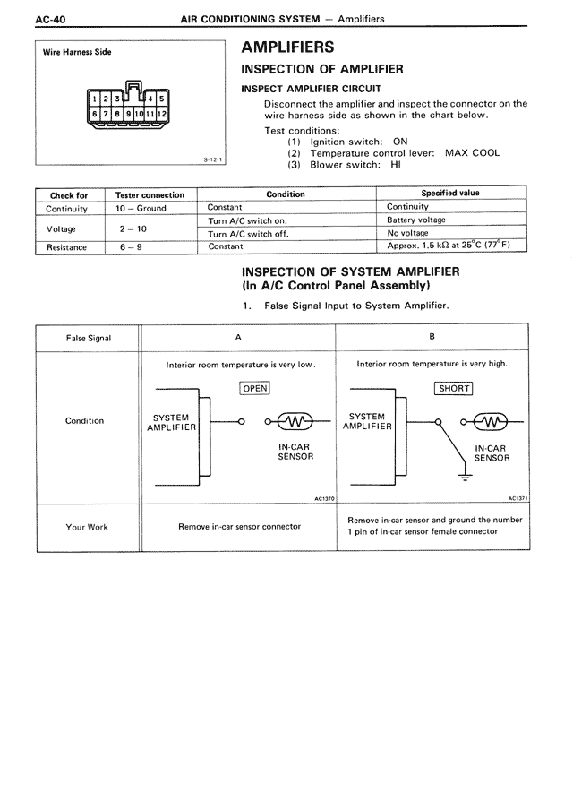
Wire Harness Side
[Diagram showing connector with pins labeled F, E, D, C, B, A and numbered 1-10]
S-12-1
AMPLIFIERS
INSPECTION OF AMPLIFIER
INSPECT AMPLIFIER CIRCUIT
Disconnect the amplifier and inspect the connector on the wire harness side as shown in the chart below.
Test conditions:
(1) Ignition switch: ON
(2) Temperature control lever: MAX COOL
(3) Blower switch: HI
Check for | Tester connection | Condition | Specified value
Continuity | 10 — Ground | Constant | Continuity
Voltage | 2 — 10 | Turn A/C switch on. | Battery voltage
| | Turn A/C switch off. | No voltage
Resistance | 6 — 9 | Constant | Approx. 1.5 kΩ at 25°C (77°F)
INSPECTION OF SYSTEM AMPLIFIER
(In A/C Control Panel Assembly)
1. False Signal Input to System Amplifier.
False Signal | A | B
Condition | Interior room temperature is very low. | Interior room temperature is very high.
| [Diagram showing SYSTEM AMPLIFIER connected to IN-CAR SENSOR marked OPEN] | [Diagram showing SYSTEM AMPLIFIER connected to IN-CAR SENSOR marked SHORT with ground]
| AC-1570 | AC-1571
Your Work | Remove in-car sensor connector | Remove in-car sensor and ground the number 1 pin of in-car sensor female connector