AT-132 AUTOMATIC TRANSMISSION — Installation of Component Parts
22. INSTALL FLANGES, PLATES AND DISCS OF OVERDRIVE BRAKE
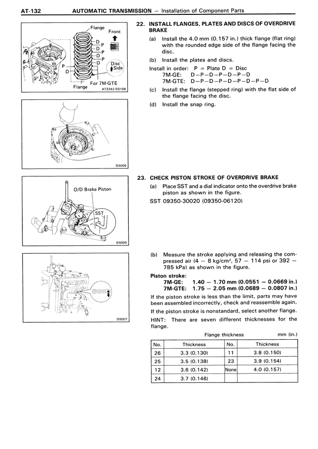
(a) Install the 4.0 mm (0.157 in.) thick flange (flat ring) with the rounded edge side of the flange facing the disc.
(b) Install the plates and discs.
Install in the following order: — Plate D — Disc D —
7M-GE: D — P — D — P — D — P — D
7M-GTE: D — P — D — P — D — P — D — P — D
(c) Install the flange (stepped ring) with the flat side of the flange facing the disc.
(d) Install the snap ring.
23. CHECK PISTON STROKE OF OVERDRIVE BRAKE
(a) Place SST and a dial indicator onto the overdrive brake piston as shown in the figure.
SST 09350-30020 (09350-06120)
(b) Measure the stroke applying and releasing the compressed air (4 — 8 kg/cm², 57 — 114 psi or 392 — 785 kPa) as shown in the figure.
Piston stroke:
7M-GE: 1.40 — 1.70 mm (0.0551 — 0.0669 in.)
7M-GTE: 1.75 — 2.05 mm (0.0689 — 0.0807 in.)
If the piston stroke is less than the limit, parts may have been assembled incorrectly, check and reassemble again.
If the piston stroke is nonstandard, select another flange.
HINT: There are seven different thicknesses for the flange.
Flange thickness mm (in.)
No. Thickness No. Thickness
26 3.3 (0.130) 11 3.8 (0.150)
25 3.5 (0.138) 23 3.9 (0.154)
12 3.6 (0.142) None 4.0 (0.157)
24 3.7 (0.146)