PRECAUTION
Do not open the cover or the case of the ECU and various computer unless absolutely necessary. (If the IC terminals are touched, the IC may be destroyed by static electricity.)
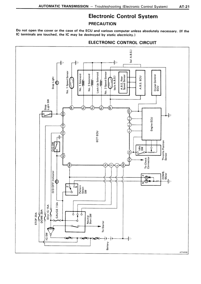
ELECTRONIC CONTROL CIRCUIT
[THIS IS DIAGRAM: Electronic control circuit diagram showing connections between various components including:
- STP Unit
- Speed Shift SW
- No. 1 Solenoid
- No. 2 Solenoid
- Lock-Up Solenoid
- No. 3 Solenoid
- Motor Control
- A/T S/L ECU
- No. S.L. ECU
- Oil Temp Sensor
- Engine Control Computer
- Engine ECU
- Throttle Position Sensor
- Inhibitor Switch
- O/D OFF SW
- CRUISE SW & SW
- Shift SW
- STOP/HA CPA F/B A/4
- Battery
- To Starter
The diagram shows electrical connections and grounding points labeled with numbers 1-10 and letters.]