AT-28 AUTOMATIC TRANSMISSION — Troubleshooting (Electronic Control System)
INSPECTION OF T₁ TERMINAL VOLTAGE
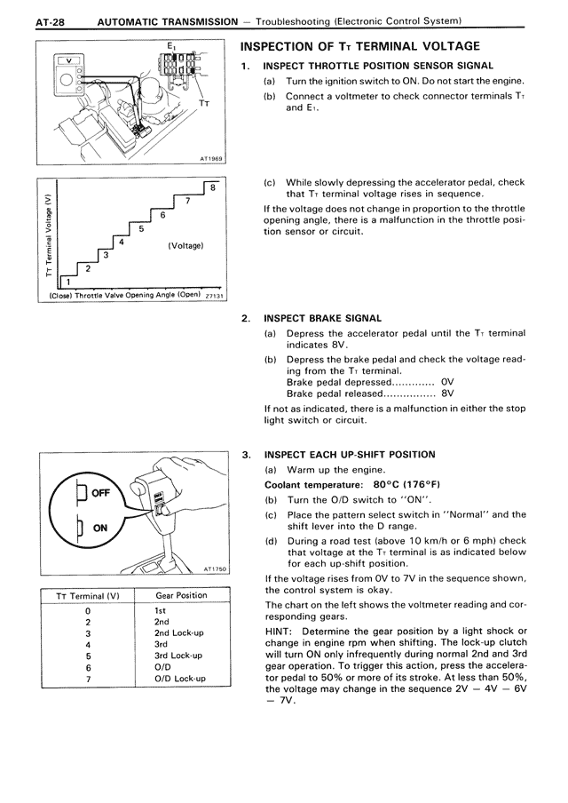
1. INSPECT THROTTLE POSITION SENSOR SIGNAL
(a) Turn the ignition switch to ON. Do not start the engine.
(b) Connect a voltmeter to check connector terminals T₁ and E₁.
(c) While slowly depressing the accelerator pedal, check that T₁ terminal voltage rises in sequence.
If the voltage does not change in proportion to the throttle opening angle, there is a malfunction in the throttle position sensor or circuit.
2. INSPECT BRAKE SIGNAL
(a) Depress the accelerator pedal until the T₁ terminal indicates 8V.
(b) Depress the brake pedal and check the voltage reading.
Brake pedal depressed.............. 0V
Brake pedal released................ 8V
If not as indicated, there is a malfunction in either the stop light switch or circuit.
3. INSPECT EACH UP-SHIFT POSITION
(a) Warm up the engine.
Coolant temperature: 80°C (176°F)
(b) Turn the O/D switch to "ON".
(c) Place the pattern select switch in "Normal" and the shift lever into the D range.
(d) During a road test (above 10 km/h or 6 mph) check that voltage at the T₁ terminal is as indicated below for each up-shift position.
If the voltage rises from 0V to 7V in the sequence shown, the control system is okay.
The chart on the left shows the voltmeter reading and corresponding gears.
HINT: Determine the gear position by a light shock or change in engine rpm when shifting. The lock-up clutch will turn ON only infrequently during normal 2nd and 3rd gear operation. To trigger this action, press the accelerator pedal to 50% or more of its stroke. At less than 50%, the voltage may change in the sequence 2V → 4V → 6V → 7V.
T₁ Terminal (V) Gear Position
0 1st
2 2nd
3 2nd Lock-up
4 3rd
5 3rd Lock-up
6 O/D
7 O/D Lock-up