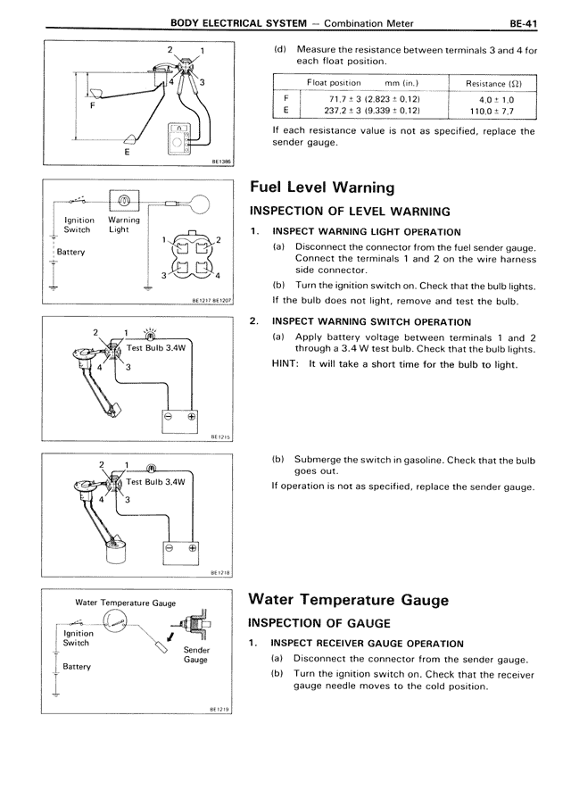
(d) Measure the resistance between terminals 3 and 4 for
each float position.
Float position mm (in.) Resistance (Ω)
F 71.7 ± 3 (2.823 ± 0.12) 4.0 ± 1.0
E 237.2 ± 3 (9.339 ± 0.12) 110.0 ± 7.0
If each resistance value is not as specified, replace the
sender gauge.
Fuel Level Warning
INSPECTION OF LEVEL WARNING
1. INSPECT WARNING LIGHT OPERATION
(a) Disconnect the connector from the fuel sender gauge.
Connect the terminals 1 and 2 on the wire harness
side connector.
(b) Turn the ignition switch on. Check that the bulb lights.
If the bulb does not light, remove and test the bulb.
2. INSPECT WARNING SWITCH OPERATION
(a) Apply battery voltage between terminals 1 and 2
through a 3.4 W test bulb. Check that the bulb lights.
HINT: It will take a short time for the bulb to light.
(b) Submerge the switch in gasoline. Check that the bulb
goes out.
If operation is not as specified, replace the sender gauge.
Water Temperature Gauge
INSPECTION OF GAUGE
1. INSPECT RECEIVER GAUGE OPERATION
(a) Disconnect the connector from the sender gauge.
(b) Turn the ignition switch on. Check that the receiver
gauge needle moves to the cold position.