Digital Type
[Image of digital multimeter]
Analog Type
[Image of analog multimeter]
FIG083
Ohmmeter
[Images showing ohmmeter connections to bulb - 4 diagrams]
Bulb
BE3623
(c) Use a volt/ohmmeter with high impedance (10 k/V minimum) for troubleshooting of the electrical circuit.
Check the Bulb
(a) Remove the bulb.
(b) There should be continuity between the respective terminals of the bulb together with a certain amount of resistance.
(c) Apply the two leads of the ohmmeter to each of the terminals.
(d) Apply battery voltage and check that the bulb light up.
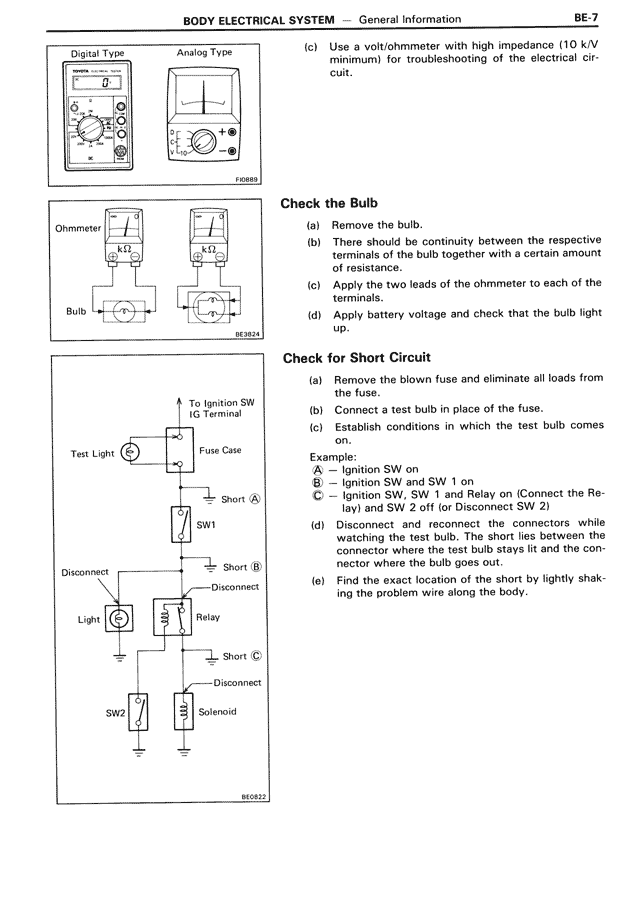
Check for Short Circuit
[Diagram showing circuit with Test Light, Fuse Case, SW1, SW2, Relay, Solenoid, and Light components, with labeled short points A, B, and C]
To Ignition SW IG Terminal
Test Light
Fuse Case
Short (A)
SW1
Disconnect
Short (B)
Disconnect
Light
Relay
Short (C)
Disconnect
SW2
Solenoid
BE0432
(a) Remove the blown fuse and eliminate all loads from the fuse.
(b) Connect a test bulb in place of the fuse.
(c) Establish conditions in which the test bulb comes on.
Example:
A — Ignition SW on
B — Ignition SW and SW 1 on
C — Ignition SW, SW 1 and Relay on (Connect the Relay) and SW 2 off (or Disconnect SW 2)
(d) Disconnect and reconnect the connectors while watching the test bulb. The short lies between the connector where the test bulb stays lit and the connector where the bulb goes out.
(e) Find the exact location of the short by lightly shaking the problem wire along the body.