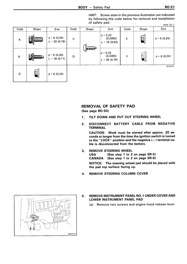
HINT: Screw sizes in the previous illustration are indicated by following the code below for removal and installation of safety pad.
[THIS IS TABLE: Screw specifications with Code, Shape, and Size columns]
Code | Shape | Size
A | [screw image] | ø = 6 (0.24), L = 20 (0.79)
B | [screw image] | ø = 5 (0.20), L = 18 (0.71)
C | [screw image] | ø = 5.22 (0.2055), L = 16 (0.63)
D | [screw image] | ø = 5.22 (0.2055), L = 20 (0.79)
E | [clip image] | ø = 6 (0.24)
F | [clip image] | ø = 6 (0.24)
G | [clip image] | ø = 6 (0.24)
HINT: Screw sizes in the previous illustration are indicated by following the code below for removal and installation of safety pad. unit in ( ): mm in (in.)
REMOVAL OF SAFETY PAD
(See page BO-50)
1. TILT DOWN AND PUT OUT STEERING WHEEL
2. DISCONNECT BATTERY CABLE FROM NEGATIVE TERMINAL
CAUTION: Work must be started after approx. 20 seconds or longer from the time the ignition switch is turned to the "LOCK" position and the negative (—) terminal cable is disconnected from the battery.
3. REMOVE STEERING WHEEL
USA (See step 1 to 2 on page SR-5)
CANADA (See step 1 to 2 on page SR-6)
NOTICE: The steering wheel pad should be placed with the pad top surface facing up.
4. REMOVE STEERING COLUMN COVER
5. REMOVE INSTRUMENT PANEL NO. 1 UNDER COVER AND LOWER INSTRUMENT PANEL PAD
(a) Remove two screws and engine hood release lever.