BRAKE SYSTEM — Anti-lock Brake System (A.B.S.)
BR-67
3. VISUALLY INSPECT SENSOR ROTOR SERRATIONS
(a) Remove the two bolts and remove the torque plate with brake cylinder.
(b) Remove the rotor disc.
(c) Inspect the sensor rotor serrations for scratches, cracks, warping or missing teeth.
(d) Install the rotor disc and brake cylinder assembly with two bolts.
Torque: 1,065 kg-cm (77 ft-lb, 104 N-m)
NOTICE: To prevent damage to the serrations, do not strike the axle hub.
4. INSPECT SENSOR ROTOR RUNOUT
Measure the sensor rotor runout at 2 mm (0.08 in.) from the serration edge.
Maximum sensor rotor runout
(the runout fluctuation measured at the top of 3 consecutive serrations): 0.1 mm (0.004 in.)
If not as specified, replace the front axle hub.
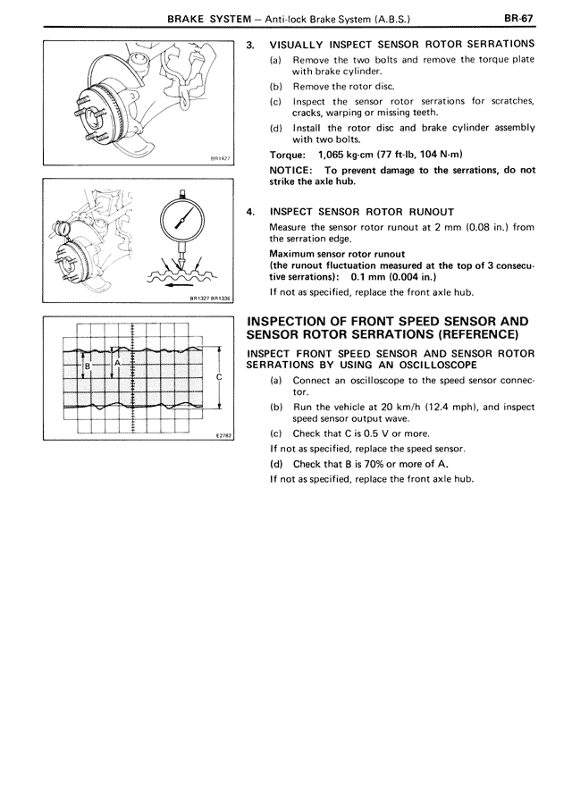
INSPECTION OF FRONT SPEED SENSOR AND SENSOR ROTOR SERRATIONS (REFERENCE)
INSPECT FRONT SPEED SENSOR AND SENSOR ROTOR SERRATIONS BY USING AN OSCILLOSCOPE
(a) Connect an oscilloscope to the speed sensor connector.
(b) Run the vehicle at 20 km/h (12.4 mph), and inspect speed sensor output wave.
(c) Check that C is 0.5 V or more.
If not as specified, replace the speed sensor.
(d) Check that B is 70% or more of A.
If not as specified, replace the front axle hub.