← 071BR · 072
BR-72 BRAKE SYSTEM — Anti-lock Brake System (A.B.S.)
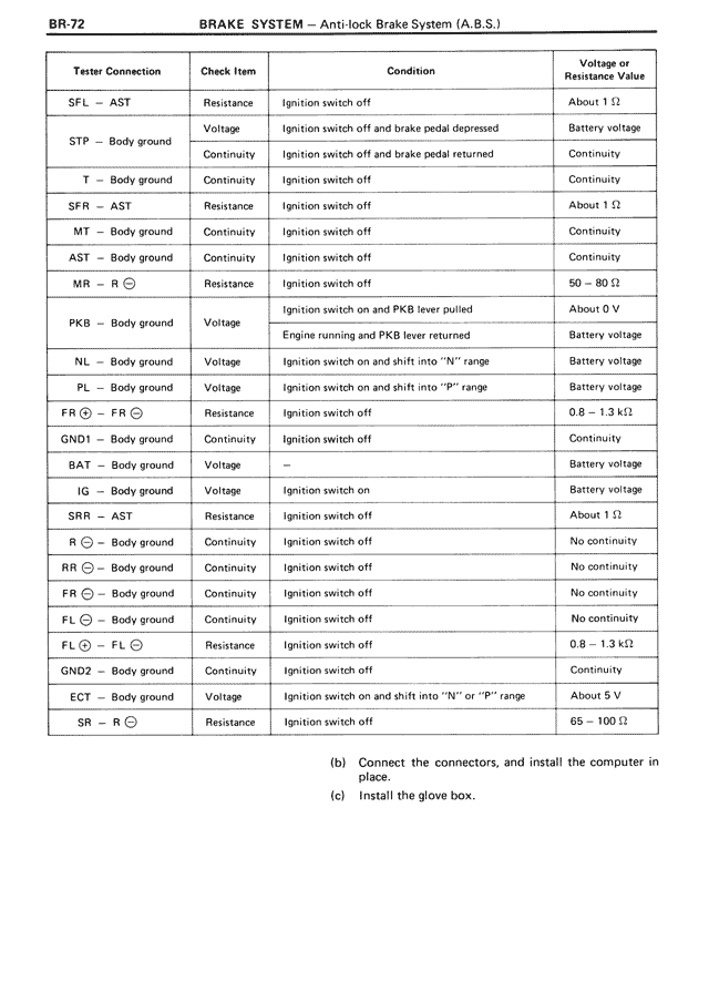
Tester Connection Check Item Condition Voltage or Resistance Value
SFL — AST Resistance Ignition switch off About 1 Ω
STP — Body ground Voltage Ignition switch off and brake pedal depressed Battery voltage
Continuity Ignition switch off and brake pedal returned Continuity
T — Body ground Continuity Ignition switch off Continuity
SFR — AST Resistance Ignition switch off About 1 Ω
MT — Body ground Continuity Ignition switch off Continuity
AST — Body ground Continuity Ignition switch off Continuity
MR — R ⊙ Resistance Ignition switch off 50 — 80 Ω
PKB — Body ground Voltage Ignition switch on and PKB lever pulled About 0 V
Engine running and PKB lever returned Battery voltage
NL — Body ground Voltage Ignition switch on and shift into "N" range Battery voltage
PL — Body ground Voltage Ignition switch on and shift into "P" range Battery voltage
FR ⊙ — FR ⊙ Resistance Ignition switch off 0.8 — 1.3 kΩ
GND1 — Body ground Continuity Ignition switch off Continuity
BAT — Body ground Voltage Battery voltage
IG — Body ground Voltage Ignition switch on Battery voltage
SRR — AST Resistance Ignition switch off About 1 Ω
R ⊙ — Body ground Continuity Ignition switch off No continuity
RR ⊙ — Body ground Continuity Ignition switch off No continuity
FR ⊙ — Body ground Continuity Ignition switch off No continuity
FL ⊙ — Body ground Continuity Ignition switch off No continuity
FL ⊙ — FL ⊙ Resistance Ignition switch off 0.8 — 1.3 kΩ
GND2 — Body ground Continuity Ignition switch off Continuity
ECT — Body ground Voltage Ignition switch on and shift into "N" or "P" range About 5 V
SR — R ⊙ Resistance Ignition switch off 65 — 100 Ω
(b) Connect the connectors, and install the computer in place.
(c) Install the glove box.