CH-14
CHARGING SYSTEM — Alternator
ASSEMBLY OF ALTERNATOR
(See page CH-6)
1. INSTALL ROTOR TO DRIVE END FRAME
2. [7M-GE (A/T) and 7M-GTE]
PLACE ALTERNATOR WASHER ON REAR BEARING
CH0636
3. INSTALL RECTIFIER END FRAME
(a) Using a plastic-faced hammer, lightly tap in the end frame.
(b) Install the four nuts.
CH0634
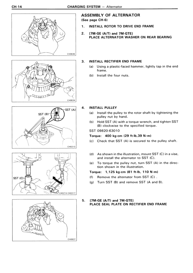
4. INSTALL PULLEY
(a) Install the pulley to the rotor shaft by tightening the pulley nut by hand.
(b) Hold SST (A) with a torque wrench, and tighten SST (B) clockwise to the specified torque.
SST 09820-63010
Torque: 400 kg-cm (29 ft-lb, 39 N·m)
(c) Check that SST (A) is secured to the pulley shaft.
(d) As shown in the illustration, mount SST (C) in a vise, and install the alternator to SST (C).
(e) To torque the pulley nut, turn SST (A) in the direction shown in the illustration.
Torque: 1,125 kg-cm (81 ft-lb, 110 N·m)
(f) Remove the alternator from SST (C).
(g) Turn SST (B) and remove SST (A and B).
SST (B)
SST (A)
CH0213
SST (C)
CH0214 CH0217
5. [7M-GE (A/T) and 7M-GTE]
PLACE SEAL PLATE ON RECTIFIER END FRAME
CH0637