FUEL EVAPORATIVE EMISSION CONTROL (EVAP) SYSTEM
[DIAGRAM: Fuel Evaporative Emission Control System showing Purge Port, Throttle Body, BVSV, Fuel Tank Cap, Check Valve, Charcoal Canister, and Fuel Tank with vapor and air flow paths marked]
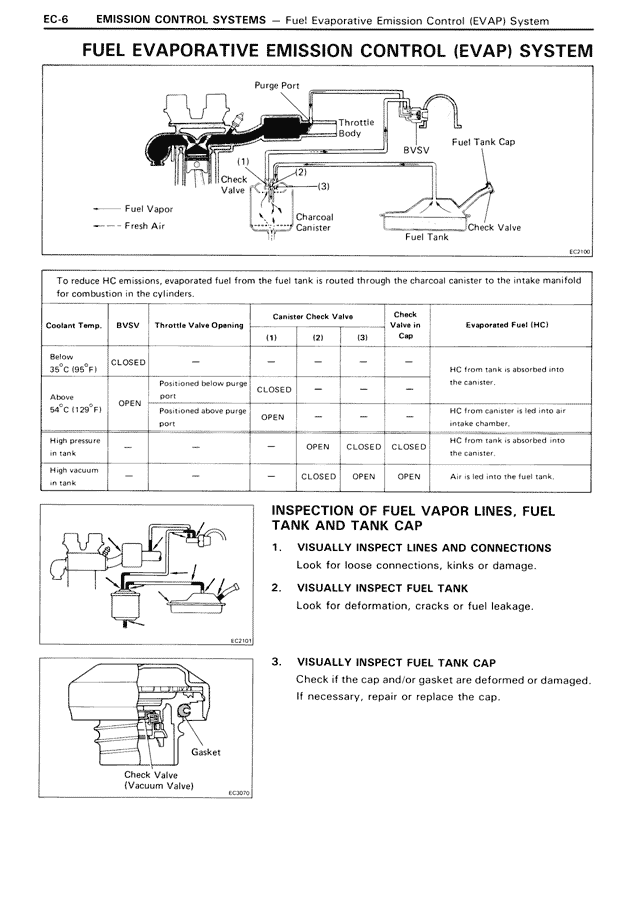
Fuel Vapor
Fresh Air
To reduce HC emissions, evaporated fuel from the fuel tank is routed through the charcoal canister to the intake manifold for combustion in the cylinders.
[TABLE: Operating conditions]
Coolant Temp. | BVSV | Throttle Valve Opening | Canister Check Valve (1) (2) (3) | Check Valve in Cap | Evaporated Fuel (HC)
Below 35°C (95°F) | CLOSED | — | Positioned below purge port | CLOSED | — | — | — | HC from tank is absorbed into the canister.
Above 35°C (129°F) | OPEN | Positioned above purge port | OPEN | — | — | — | HC from canister is led into air intake chamber.
High pressure in tank | — | — | OPEN | CLOSED | CLOSED | HC from tank is absorbed into the canister.
High vacuum in tank | — | — | — | CLOSED | OPEN | OPEN | Air is led into the fuel tank.
[DIAGRAM: Inspection diagram showing fuel vapor lines and connections]
INSPECTION OF FUEL VAPOR LINES, FUEL TANK AND TANK CAP
1. VISUALLY INSPECT LINES AND CONNECTIONS
Look for loose connections, kinks or damage.
2. VISUALLY INSPECT FUEL TANK
Look for deformation, cracks or fuel leakage.
[DIAGRAM: Fuel tank cap with Check Valve (Vacuum Valve) and Gasket]
3. VISUALLY INSPECT FUEL TANK CAP
Check if the cap and/or gasket are deformed or damaged.
If necessary, repair or replace the cap.
Check Valve
(Vacuum Valve)
Gasket