EM-96 ENGINE MECHANICAL — Cylinder Block
[DIAGRAM: Shows mechanical component installation]
EM2601
22. CONNECT FOLLOWING CONNECTORS AND WIRES:
(a) ECU and ECT connectors
(b) Ground strap to engine rear side
(c) Heater valve connector
(d) (7M-GE)
Oxygen sensor connector
(e) Alternator connector and wire
(f) Main relay connector
(g) (7M-GE)
Ignition coil connector
(7M-GTE)
Igniter connector
(h) (7M-GTE)
Solenoid resister connector
(i) Check connector
(j) Theft deterrent horn connector
(k) Noise filter connector
(l) Battery positive cable to battery
(m) Ground strap to LH front fender apron
23. CONNECT FOLLOWING HOSES:
(a) Charcoal canister hose
(b) Cruise control hose
(c) Heater valve hose
(d) Brake booster hose
24. INSTALL PS BELT
(See page MA-4)
25. INSTALL ALTERNATOR DRIVE BELT, WATER PUMP
PULLEY AND FLUID COUPLING
(See page CO-7)
26. INSTALL A/C BELT
(See page MA-4)
27. INSTALL RADIATOR
(See page CO-14)
[DIAGRAM: Shows engine component detail]
EM6261
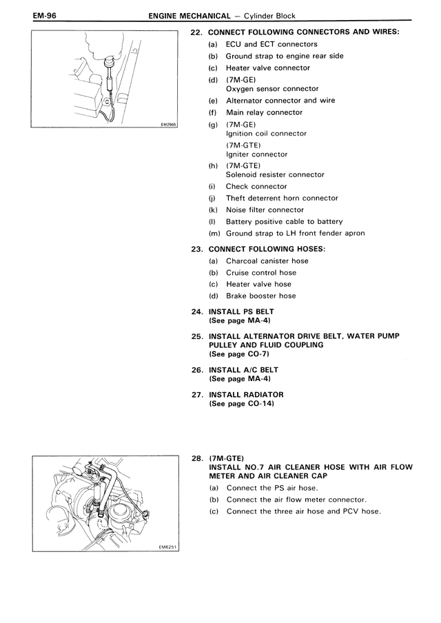
28. (7M-GTE)
INSTALL NO.7 AIR CLEANER HOSE WITH AIR FLOW
METER AND AIR CLEANER CAP
(a) Connect the PS air hose.
(b) Connect the air flow meter connector.
(c) Connect the three air hose and PCV hose.