3. CHECK THROTTLE POSITION SENSOR
(See step 2 on page FI-101)
4. IF NECESSARY, ADJUST THROTTLE POSITION SENSOR
(a) Loosen the two screws of the sensor.
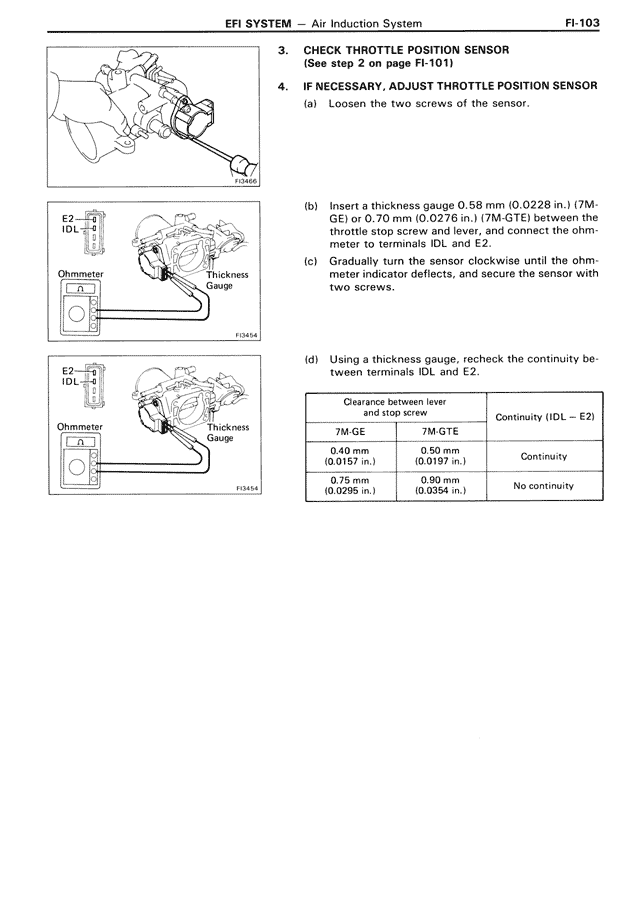
(b) Insert a thickness gauge 0.58 mm (0.0228 in.) (7M-GE) or 0.70 mm (0.0276 in.) (7M-GTE) between the throttle stop screw and lever, and connect the ohmmeter to terminals IDL and E2.
(c) Gradually turn the sensor clockwise until the ohmmeter indicator deflects, and secure the sensor with two screws.
(d) Using a thickness gauge, recheck the continuity between terminals IDL and E2.
Clearance between lever
and stop screw Continuity (IDL — E2)
7M-GE 7M-GTE
0.40 mm 0.50 mm
(0.0157 in.) (0.0197 in.) Continuity
0.75 mm 0.90 mm
(0.0295 in.) (0.0354 in.) No continuity