100%
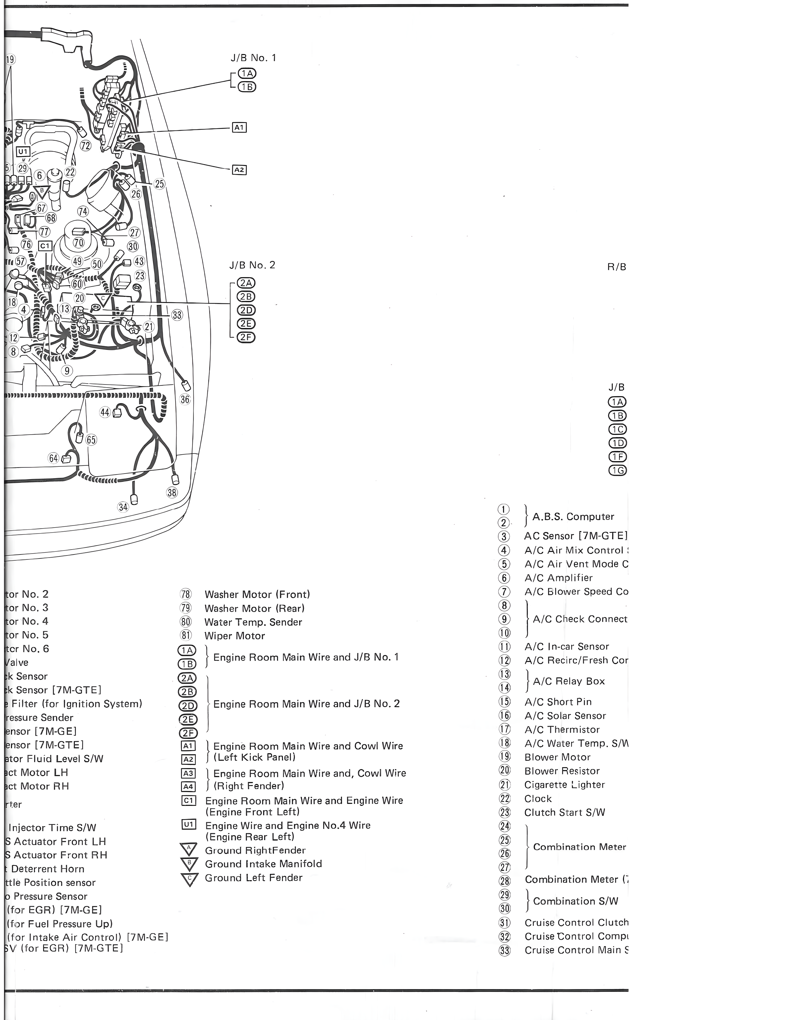
J/B No. 1
1A
1B
A1
A2
J/B No. 2
2A
2B
2C
2D
2E
2F
R/B
J/B
1A
1B
1C
1D
1E
1G
(1)
(2)
A.B.S. Computer
(3)
AC Sensor [7M-GTE]
(4)
A/C Air Mix Control [
(5)
A/C Air Vent Mode C
(6)
A/C Amplifier
(7)
A/C Blower Speed Co
(8)
(9)
A/C Check Connect
(10)
(11)
A/C In-car Sensor
(12)
A/C Recric/Fresh Cor
(13)
A/C Relay Box
(14)
(15)
A/C Short Pin
(16)
A/C Solar Sensor
(17)
A/C Thermistor
(18)
A/C Water Temp. S/W
(19)
Blower Motor
(20)
Blower Resistor
(21)
Cigarette Lighter
(22)
Clock
(23)
Clutch Start S/W
(24)
(25)
Combination Meter
(26)
(27)
(28)
Combination Meter (;
(29)
Combination S/W
(30)
(31)
Cruise Control Clutch
(32)
Cruise Control Compu
(33)
Cruise Control Main S
for No. 2
78
Washer Motor (Front)
for No. 3
79
Washer Motor (Rear)
for No. 4
80
Water Temp. Sender
for No. 5
81
Wiper Motor
for No. 6
1A
Engine Room Main Wire and J/B No. 1
Valve
1B
k Sensor
2A
ck Sensor [7M-GTE]
2B
k Filter (for Ignition System)
2D
Engine Room Main Wire and J/B No. 2
ressure Sender
2E
ensor [7M-GE]
2F
ensor [7M-GTE]
A1
Engine Room Main Wire and Cowl Wire
Motor Fluid Level S/W
A2
(Left Kick Panel)
ct Motor LH
A3
Engine Room Main Wire and, Cowl Wire
ct Motor RH
A4
(Right Fender)
C1
Engine Room Main Wire and Engine Wire
ter
(Engine Front Left)
Injector Time S/W
U1
Engine Wire and Engine No.4 Wire
(Engine Rear Left)
S Actuator Front LH
Ground RightFender
S Actuator Front RH
Ground Intake Manifold
Deterrent Horn
Ground Left Fender
ttle Position sensor
o Pressure Sensor
(for EGR) [7M-GE]
(for Fuel Pressure Up)
(for Intake Air Control) [7M-GE]
PCV (for EGR) [7M-GTE]