100%
REAR WIPER AND WASHER 17
20A WIPER
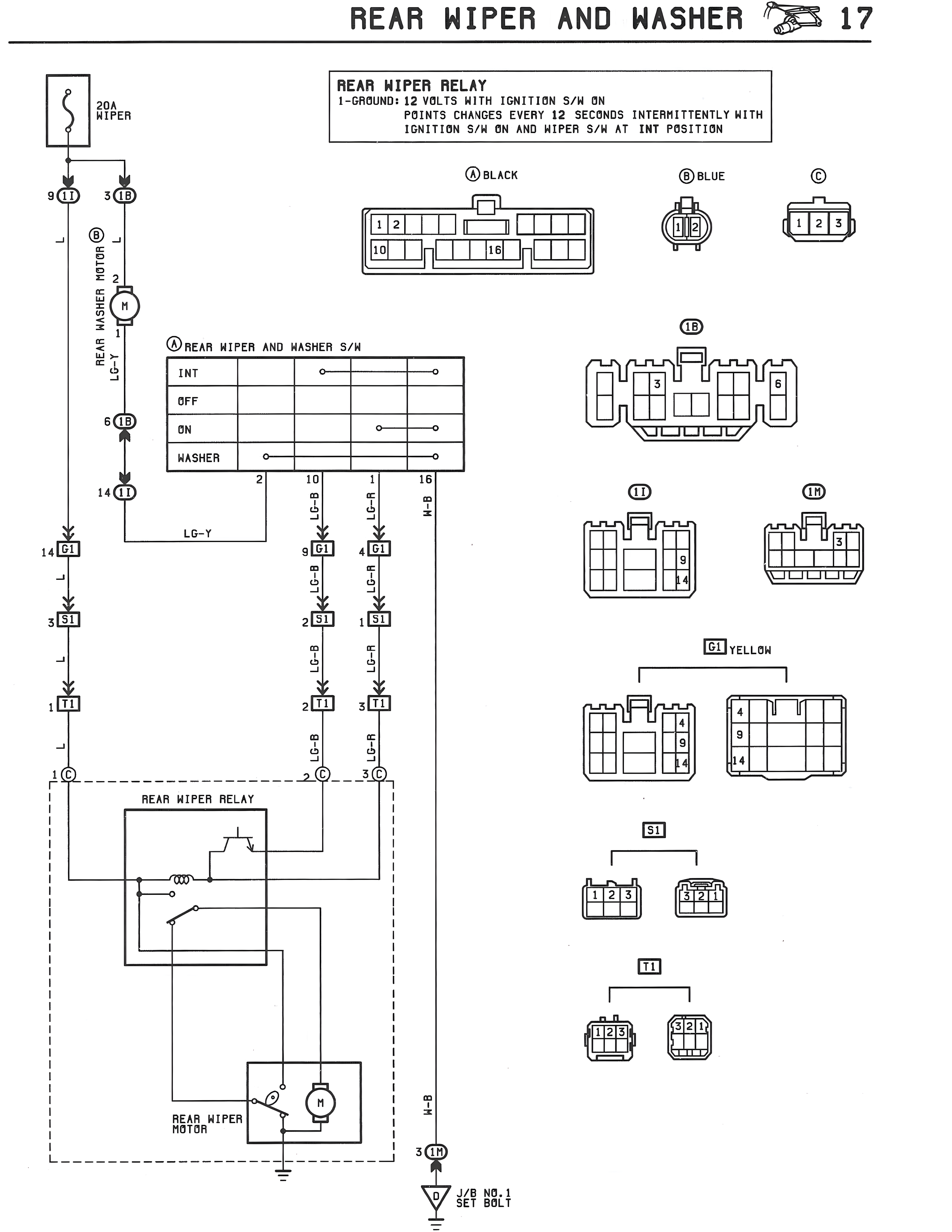
REAR WIPER RELAY
1-GROUND: 12 VOLTS WITH IGNITION S/W ON
POINTS CHANGES EVERY 12 SECONDS INTERMITTENTLY WITH
IGNITION S/W ON AND WIPER S/W AT INT POSITION
A BLACK B BLUE C
[Connector diagrams showing:
- Connector A: BLACK with numbered pins 1, 2, 10, 1B
- Connector B: BLUE with 2 pins
- Connector C: 3-pin connector with pins 1, 2, 3]
1B
[Connector diagram showing 5 pins numbered 1, 2, 3, 5]
II III
[Connector diagrams showing:
- II: 4 pins with pins 9, 4 marked
- III: 5 pins with pin 9 marked]
G1 YELLOW
[Two connector diagrams showing 4-pin and 5-pin configurations with pin 9 and pin 4 marked]
S1
[Two 3-pin connector diagrams showing pins 1, 2, 3 and 1, 2, 1]
I1
[Two 3-pin connector diagrams showing pins 1, 2, 3]
A REAR WIPER AND WASHER S/W
[Switch diagram showing:
INT
OFF
ON
WASHER
with connections to pins 2, 10, 1, 1B]
LG-Y
LG-R LG-R W-B
9 G1 4 G1 1B
B-GR B-GR
2 S1 1 S1
G-B G-R
2 I1 3 I1
B-R B-R
2 C 3 C
REAR WIPER RELAY
[Relay circuit diagram showing internal relay components and connections to REAR WIPER MOTOR]
W-B
3 1B
3/8 NO.1 SET BOLT
9 I1 3 1B
6 1B
14 I1
14 I1
3 S1
1 I1
1 C
B REAR WASHER MOTOR
REAR WIPER MOTOR