100%
AIR CONDITIONING SYSTEM — Relays
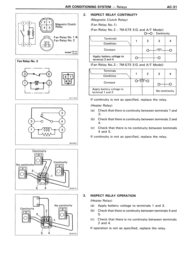
[Diagram showing Magnetic Clutch Relay with terminals 1-4 and Fan Relay No. 1 & Fan Relay No. 2]
Fan Relay No. 3
[Diagram showing relay terminals 1-4 with coil]
[Diagram showing Heater Relay terminals 1-5]
[Two diagrams showing continuity testing points with numbered terminals]
2. INSPECT RELAY CONTINUITY
(Magnetic Clutch Relay)
(Fan Relay No.1)
(Fan Relay No.2 ; 7M-GTE E/G and A/T Model)
Terminals
Condition | 1 | 2 | 3 | 4
Constant | [continuity symbol shown between terminals]
Apply battery voltage to terminal 2 and 4 | [continuity symbol shown between terminals]
(Fan Relay No.3 ; 7M-GTE E/G and A/T Model)
Terminals
Condition | 1 | 2 | 3 | 4
Constant | [continuity symbol shown]
Apply battery voltage to terminal 1 and 2 | No continuity
If continuity is not as specified, replace the relay.
(Heater Relay)
(a) Check that there is continuity between terminals 1 and 3.
(b) Check that there is continuity between terminals 2 and 4.
(c) Check that there is no continuity between terminals 4 and 5.
If continuity is not as specified, replace the relay.
3. INSPECT RELAY OPERATION
(Heater Relay)
(a) Apply battery voltage to terminals 1 and 3.
(b) Check that there is continuity between terminals 4 and 5.
(c) Check that there is no continuity between terminals 2 and 4.
If operation is not as specified, replace the relay.