100%
AUTOMATIC TRANSMISSION — Troubleshooting (Electronic Control System) AT-29
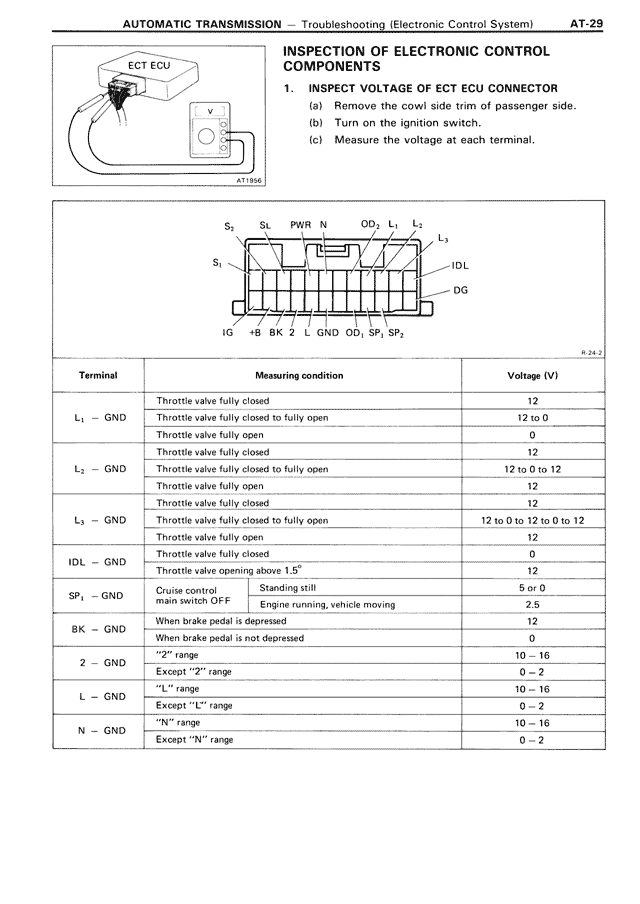
INSPECTION OF ELECTRONIC CONTROL COMPONENTS
1. INSPECT VOLTAGE OF ECT ECU CONNECTOR
(a) Remove the cowl side trim of passenger side.
(b) Turn on the ignition switch.
(c) Measure the voltage at each terminal.
[Diagram showing ECT ECU connector with voltmeter]
[Diagram showing ECT ECU connector pinout with terminals labeled:
S₂ SL PWR N OD₁ L₁ L₂
L₃
S₁ IDL
DG
IG +B BK 2 L GND OD₁ SP₁ SP₂]
Terminal Measuring condition Voltage (V)
L₁ — GND Throttle valve fully closed 12
Throttle valve fully closed to fully open 12 to 0
Throttle valve fully open 0
L₂ — GND Throttle valve fully closed 12
Throttle valve fully closed to fully open 12 to 0 to 12
Throttle valve open 12
L₃ — GND Throttle valve fully closed 12
Throttle valve fully closed to fully open 12 to 0 to 12 to 0 to 12
Throttle valve open 12
IDL — GND Throttle valve fully closed 0
Throttle valve opening above 1.5° 12
SP₁ — GND Cruise control Standing still 5 or 0
main switch OFF Engine running, vehicle moving 2.5
BK — GND When brake pedal is depressed 12
When brake pedal is not depressed 0
2 — GND "2" range 10 ~ 16
Except "2" range 0 ~ 2
L — GND "L" range 10 ~ 16
Except "L" range 0 ~ 2
N — GND "N" range 10 ~ 16
Except "N" range 0 ~ 2