100%
BE-42
BODY ELECTRICAL SYSTEM — Combination Meter
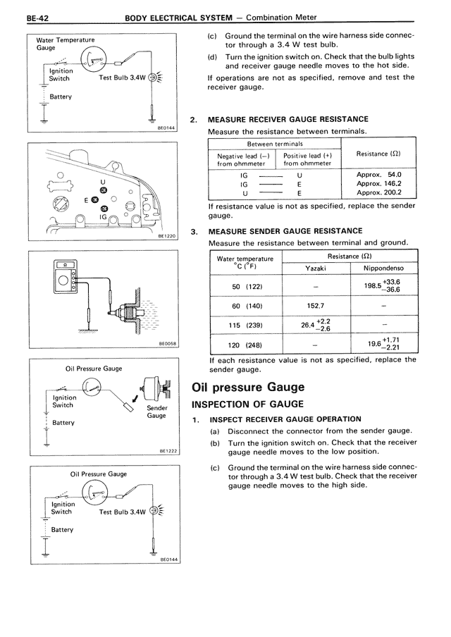
Water Temperature Gauge
Ignition Switch
Test Bulb 3-4W
Battery
BE0141
U
IG
E
IG
BE1320
BE0058
Oil Pressure Gauge
Ignition Switch
Sender Gauge
Battery
BE1322
Oil Pressure Gauge
Ignition Switch
Test Bulb 3-4W
Battery
BE0144
(c) Ground the terminal on the wire harness side connector through a 3.4 W test bulb.
(d) Turn the ignition switch on. Check that the bulb lights and receiver gauge needle moves to the hot side.
If operations are not as specified, remove and test the receiver gauge.
2. MEASURE RECEIVER GAUGE RESISTANCE
Measure the resistance between terminals.
Between terminals
Negative lead (–) from ohmmeter | Positive lead (+) from ohmmeter | Resistance (Ω)
IG | U | Approx. 54.0
IG | E | Approx. 146.2
U | E | Approx. 200.2
If resistance value is not as specified, replace the sender gauge.
3. MEASURE SENDER GAUGE RESISTANCE
Measure the resistance between terminal and ground.
Water temperature C (°F) | Resistance (Ω)
| Yazaki | Nippodemo
50 (122) | — | 198.5 +33.6/-36.6
60 (140) | 152.7 | —
115 (239) | 26.4 +2.2/-2.6 | —
120 (248) | — | 19.6 +1.71/-2.21
If each resistance value is not as specified, replace the sender gauge.
Oil pressure Gauge
INSPECTION OF GAUGE
1. INSPECT RECEIVER GAUGE OPERATION
(a) Disconnect the connector from the sender gauge.
(b) Turn the ignition switch on. Check that the receiver gauge needle moves to the low position.
(c) Ground the terminal on the wire harness side connector through a 3.4 W test bulb. Check that the receiver gauge needle moves to the high side.