100%
BE-46
BODY ELECTRICAL SYSTEM — Combination Meter
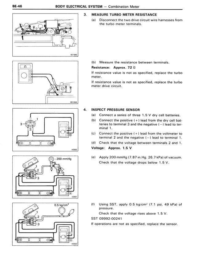
3. MEASURE TURBO METER RESISTANCE
(a) Disconnect the two drive circuit wire harnesses from the turbo meter terminals.
(b) Measure the resistance between terminals.
Resistance: Approx. 72 Ω
If resistance value is not as specified, replace the turbo meter.
If resistance value is not as specified, replace the turbo meter drive circuit.
4. INSPECT PRESSURE SENSOR
(a) Connect a series of three 1.5 V dry cell batteries.
(b) Connect the positive (+) lead from the dry cell batteries to terminal 3 and the negative (—) lead to terminal 1.
(c) Connect the positive (+) lead from the voltmeter to terminal 2 and the negative (—) lead to terminal 1.
(d) Check that the voltage between terminals 2 and 1.
Voltage: Approx. 1.5 V
(e) Apply 200 mmHg (7.87 in.Hg, 26.7 kPa) of vacuum.
Check that the voltage drops below 1.5 V.
(f) Using SST, apply 0.5 kg/cm² (7.1 psi, 49 kPa) of pressure.
Check that the voltage rises above 1.5 V.
SST 09992-00241
If operations are not as specified, replace the sensor.