100%
BE-80
BODY ELECTRICAL SYSTEM — Cruise Control System
Wire Harness Side
[Diagram showing connector pins labeled 1|2|3 4|5 6|7|8|9 10|11 12|13|14 15|16|17]
5-W1
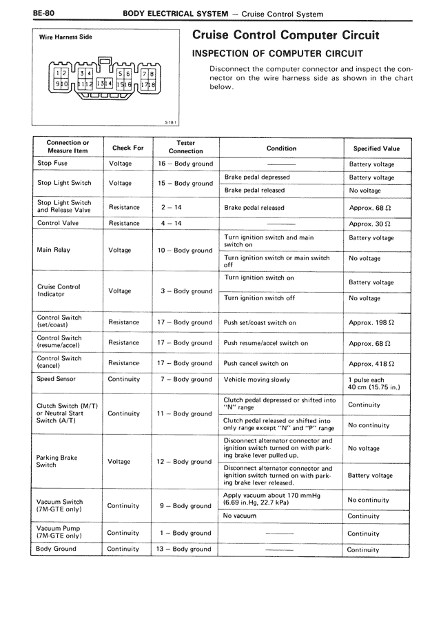
Cruise Control Computer Circuit
INSPECTION OF COMPUTER CIRCUIT
Disconnect the computer connector and inspect the connector on the wire harness side as shown in the chart below.
Connection or
Measure Item | Check For | Tester Connection | Condition | Specified Value
Stop Fuse | Voltage | 16 - Body ground | Brake pedal depressed | Battery voltage
Stop Light Switch | Voltage | 15 - Body ground | Brake pedal released | No voltage
Stop Light Switch
and Release Valve | Resistance | 2 - 14 | Brake pedal released | Approx. 68 Ω
Control Valve | Resistance | 4 - 14 | — | Approx. 30 Ω
Main Relay | Voltage | 10 - Body ground | Turn ignition switch and main switch on | Battery voltage
Main Relay | Voltage | 10 - Body ground | Turn ignition switch or main switch off | No voltage
Cruise Control
Indicator | Voltage | 3 - Body ground | Turn ignition switch on | Battery voltage
Cruise Control
Indicator | Voltage | 3 - Body ground | Turn ignition switch off | No voltage
Control Switch
(set/coast) | Resistance | 17 - Body ground | Push set/coast switch on | Approx. 198 Ω
Control Switch
(resume/accel) | Resistance | 17 - Body ground | Push resume/accel switch on | Approx. 68 Ω
Control Switch
(cancel) | Resistance | 17 - Body ground | Push cancel switch on | Approx. 418 Ω
Speed Sensor | Continuity | 7 - Body ground | Vehicle moving slowly | 1 pulse each
40 cm (15.75 in.)
Clutch Switch (M/T)
or Neutral Start
Switch (A/T) | Continuity | 11 - Body ground | Clutch pedal depressed or shifted into
"N" range | Continuity
Clutch Switch (M/T)
or Neutral Start
Switch (A/T) | Continuity | 11 - Body ground | Clutch pedal released or shifted into
only range except "N" and "P" range | No continuity
Parking Brake
Switch | Voltage | 12 - Body ground | Disconnect alternator connector and
ignition switch turned on with parking brake lever pulled up | No voltage
Parking Brake
Switch | Voltage | 12 - Body ground | Disconnect alternator connector and
ignition switch turned on with parking brake lever released. | Battery voltage
Vacuum Switch
(7M-GTE only) | Continuity | 9 - Body ground | Apply vacuum about 170 mmHg
(0.03 in.Hg, 22.7 kPa) | No continuity
Vacuum Switch
(7M-GTE only) | Continuity | 9 - Body ground | No vacuum | Continuity
Vacuum Pump
(7M-GTE only) | Continuity | 1 - Body ground | — | Continuity
Body Ground | Continuity | 13 - Body ground | — | Continuity