100%
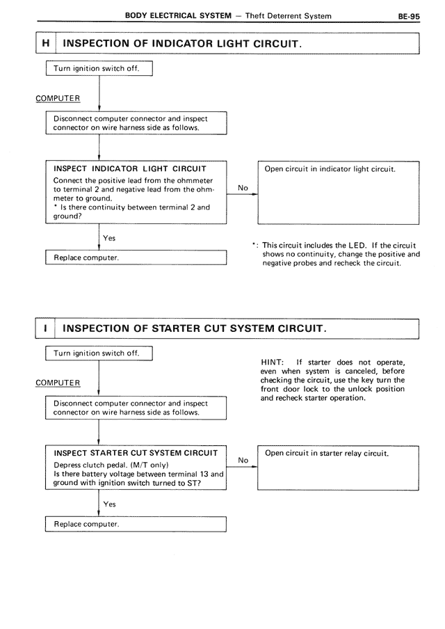
H INSPECTION OF INDICATOR LIGHT CIRCUIT.
Turn ignition switch off.
COMPUTER
Disconnect computer connector and inspect
connector on wire harness side as follows.
INSPECT INDICATOR LIGHT CIRCUIT
Connect the positive lead from the ohmmeter
to terminal 2 and negative lead from the ohm-
meter to ground.
* Is there continuity between terminal 2 and
ground?
No
Open circuit in indicator light circuit.
*: This circuit includes the LED. If the circuit
shows no continuity, change the positive and
negative probes and recheck the circuit.
Yes
Replace computer.
I INSPECTION OF STARTER CUT SYSTEM CIRCUIT.
Turn ignition switch off.
HINT: If starter does not operate,
even when system is cancelled, before
checking the circuit, use the key turn the
front door lock to the unlock position
and recheck starter operation.
COMPUTER
Disconnect computer connector and inspect
connector on wire harness side as follows.
INSPECT STARTER CUT SYSTEM CIRCUIT
Depress clutch pedal. (M/T only)
Is there battery voltage between terminal 13 and
ground with ignition switch turned to ST?
No
Open circuit in starter relay circuit.
Yes
Replace computer.