100%
A.B.S. Actuator
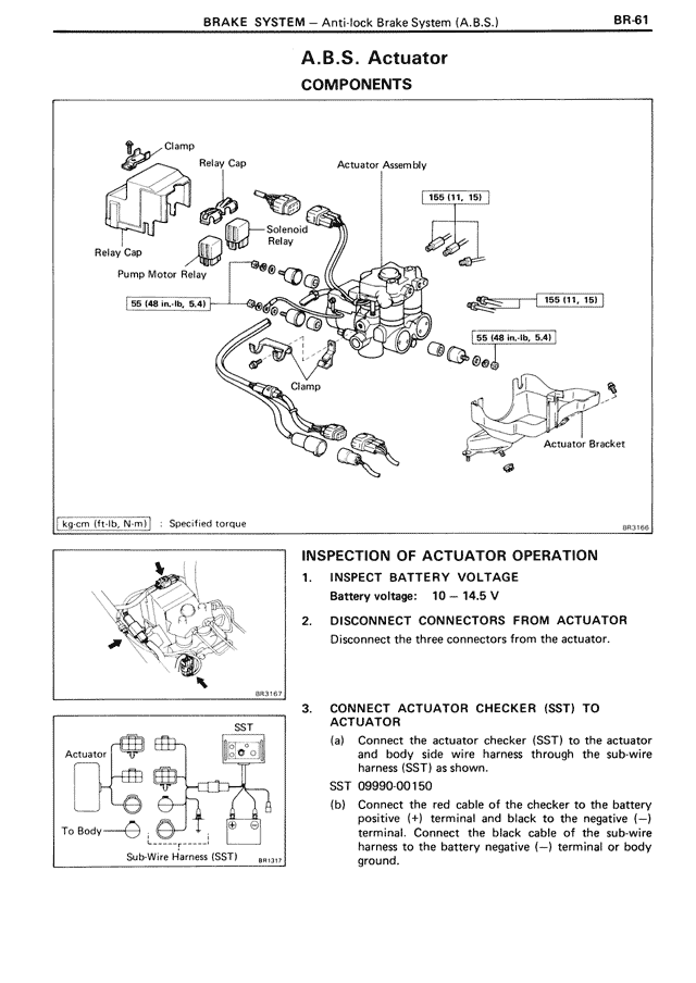
COMPONENTS
Clamp
Relay Cap
Actuator Assembly
155 (11, 15)
Relay Cap
Solenoid Relay
Pump Motor Relay
155 (11, 15)
95 (48 in.-lb, 5.4)
55 (48 in.-lb, 5.4)
Clamp
Actuator Bracket
kg-cm (ft-lb, N·m) : Specified torque
BR3165
INSPECTION OF ACTUATOR OPERATION
1. INSPECT BATTERY VOLTAGE
Battery voltage: 10 — 14.5 V
2. DISCONNECT CONNECTORS FROM ACTUATOR
Disconnect the three connectors from the actuator.
BR3167
3. CONNECT ACTUATOR CHECKER (SST) TO ACTUATOR
(a) Connect the actuator checker (SST) to the actuator and body side wire harness through the sub-wire harness (SST) as shown.
SST 09990-00150
(b) Connect the red cable of the checker to the battery positive (+) terminal and black to the negative (—) terminal. Connect the black cable of the sub-wire harness to the battery negative (—) terminal or body ground.
SST
Actuator
To Body
Sub-Wire Harness (SST)
BR3133