100%
BRAKE SYSTEM — Anti-lock Brake System (A.B.S.) BR-71
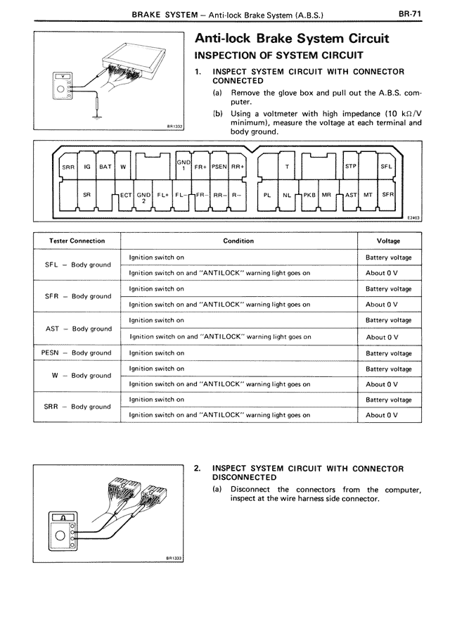
Anti-lock Brake System Circuit
INSPECTION OF SYSTEM CIRCUIT
1. INSPECT SYSTEM CIRCUIT WITH CONNECTOR CONNECTED
(a) Remove the glove box and pull out the A.B.S. computer.
(b) Using a voltmeter with high impedance (10 kΩ/V minimum), measure the voltage at each terminal and body ground.
[CONNECTOR DIAGRAM showing terminals: SRR, IG, BAT, W, SR, ELECT GND, ELL +, GNF FR, FFR, RR+, FSEN RR+, T, PL, INL, +TKR, MR, +LAST, MT, SFR, SFL, SPL, STR]
Tester Connection | Condition | Voltage
SFL — Body ground | Ignition switch on | Battery voltage
| Ignition switch on and "ANTILOCK" warning light goes on | About 0 V
SFR — Body ground | Ignition switch on | Battery voltage
| Ignition switch on and "ANTILOCK" warning light goes on | About 0 V
AST — Body ground | Ignition switch on | Battery voltage
| Ignition switch on and "ANTILOCK" warning light goes on | About 0 V
FESN — Body ground | Ignition switch on | Battery voltage
W — Body ground | Ignition switch on | Battery voltage
| Ignition switch on and "ANTILOCK" warning light goes on | About 0 V
SRR — Body ground | Ignition switch on | Battery voltage
| Ignition switch on and "ANTILOCK" warning light goes on | About 0 V
2. INSPECT SYSTEM CIRCUIT WITH CONNECTOR DISCONNECTED
(a) Disconnect the connectors from the computer, inspect at the wire harness side connector.