100%
ELECTRICAL WIRING
DIAGRAMS
HOW TO READ THIS SECTION
PIN NUMBER
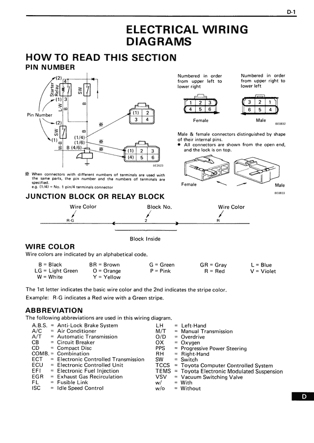
Pin Number
Numbered in order
from upper left to
lower right
Numbered in order
from upper right to
lower left
[1] [2]
[3] [4]
1 2 3
4 5 6
Female
812929
3 2 1
6 5 4
Male
Male & female connectors distinguished by shape
of their internal pins.
• All connectors are shown from the open end,
and the lock is on top.
Female
812933
Male
※ When connectors with different numbers of terminals are used with
the same parts, the pin number and the numbers of terminals are
specified.
e.g. (1/4) = No. 1 pin/4 terminals connector
JUNCTION BLOCK OR RELAY BLOCK
Wire Color Block No. Wire Color
R-G Z R
Block Inside
WIRE COLOR
Wire colors are indicated by an alphabetical code.
B = Black BR = Brown G = Green GR = Gray L = Blue
LG = Light Green O = Orange P = Pink R = Red V = Violet
W = White Y = Yellow
The 1st letter indicates the basic wire color and the 2nd indicates the stripe color.
Example: R-G indicates a Red wire with a Green stripe.
ABBREVIATION
The following abbreviations are used in this wiring diagram.
A.B.S. = Anti-Lock Brake System LH = Left-Hand
A/C = Air Conditioner M/T = Manual Transmission
A/T = Automatic Transmission O/D = Overdrive
CB = Circuit Breaker P = Park
CD = Compact Disc PPS = Progressive Power Steering
COMB. = Combination RH = Right-Hand
ECT = Electronic Controlled Transmission SW = Switch
ECU = Electronic Controlled Unit TCCS = Toyota Computer Controlled System
EFI = Electronic Fuel Injection TEMS = Toyota Electronic Modulated Suspension
EGR = Exhaust Gas Recirculation VSV = Vacuum Switching Valve
F = Fuse w = With
ISC = Idle Speed Control w/o = Without