Page text (OCR transcript)
EM-70

ENGINE MECHANICAL — Cylinder Block

No. 1 - No. 3 Crank Pin
Mark
1 or 2

No. 4 - No. 6 Crank Pin

Front

Mark
1, 2, 3, 4
or 5

Mark
1, 2 or 3

SW0698
E0735 EM0553

EM4533

EM1792

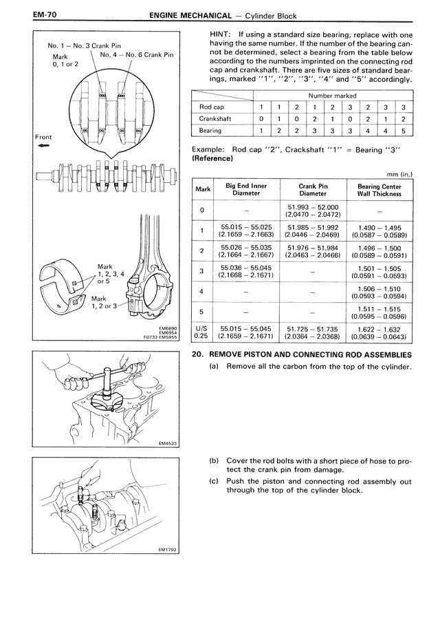
HINT: If using a standard size bearing, replace with one having the same number. If the number of the bearing cannot be determined, select a bearing from the table below according to the numbers imprinted on the connecting rod cap and crankshaft. There are five sizes of standard bearings, marked "1", "2", "3", "4" and "5" accordingly.

[THIS IS TABLE: Number marked table showing Rod cap, Crankshaft, and Bearing relationships]
Number marked
         1  1  2  1  2  2  3  3
Rod cap  1  1  2  1  2  2  3  3
Crankshaft 0  1  0  2  1  0  2  1  2
Bearing  1  2  3  2  3  3  4  4  5

Example: Rod cap "2", Crackshaft "1" = Bearing "3"
(Reference)

mm (in.)
[THIS IS TABLE: Bearing specifications table with columns for Mark, Big End Inner Diameter, Crank Pin Diameter, and Bearing Center Wall Thickness]

Mark  Big End Inner           Crank Pin              Bearing Center
      Diameter                Diameter               Wall Thickness

0                             51.993 - 52.000
                              (2.0470 - 2.0472)

1     55.015 - 55.025         51.985 - 51.992        1.490 - 1.495
      (2.1659 - 2.1663)       (2.0466 - 2.0469)      (0.0587 - 0.0589)

2     55.026 - 55.035         51.976 - 51.984        1.496 - 1.501
      (2.1664 - 2.1667)       (2.0463 - 2.0466)      (0.0589 - 0.0591)

3     55.036 - 55.045                                1.496 - 1.501
      (2.1668 - 2.1671)                              (0.0591 - 0.0593)

4                                                    1.508 - 1.510
                                                     (0.0593 - 0.0594)

5                                                    1.511 - 1.515
                                                     (0.0595 - 0.0596)

U/S   55.015 - 55.045         51.725 - 51.735        1.622 - 1.632
0.25  (2.1659 - 2.1671)       (2.0364 - 2.0368)      (0.0639 - 0.0643)

20. REMOVE PISTON AND CONNECTING ROD ASSEMBLIES

(a) Remove all the carbon from the top of the cylinder.

(b) Cover the rod bolts with a short piece of hose to protect the crank pin from damage.

(c) Push the piston and connecting rod assembly out through the top of cylinder block.