Page text (OCR transcript)
ENGINE MECHANICAL — Cylinder Block                                    EM-73

(Reference)
                                                                       mm (in.)

           Mark
        1, 2, 3, 4 or 5


Front
  ←    [DIAGRAM SHOWING CYLINDER JOURNALS]

No. 1 — No. 4 Journal
       No. 5 — No. 7 Journal
Mark
1, 2 or 3


                                    Mark  Cylinder Block         Main Journal      Bearing Center
                                          Main Journal Bore      Diameter          Wall Thickness

                                    0     —                      69.007 — 69.012   —
                                                                 (2.5025 — 2.5027)

                                    1     64.024 — 64.030        69.001 — 69.006   1.988 — 1.991
                                          (2.5206 — 2.5209)      (2.3622 — 2.3624) (0.0783 — 0.0784)

                                    2     64.031 — 64.036        59.994 — 60.000   1.982 — 1.994
                                          (2.5209 — 2.5211)      (2.3620 — 2.3622) (0.0784 — 0.0786)

                                    3     64.037 — 64.042        —                 1.995 — 1.997
                                          (2.5211 — 2.5213)                        (0.0785 — 0.0786)

                                    4     —                      —                 1.998 — 2.000
                                                                                   (0.0787 — 0.0787)

                                    5     —                      —                 2.001 — 2.003
                                                                                   (0.0788 — 0.0789)

                                    U/S   64.022 — 64.046        59.730 — 59.740   2.023 — 2.025
                                    0.25  (2.5205 — 2.5215)      (2.3516 — 2.3520) (0.0796 — 0.0840)


                        EO738
                        C5661

[DIAGRAM SHOWING BEARING CAP POSITIONS]
Upper                                        1  2  3  4  5  6  7
                                          Lower
                                                            EM3839

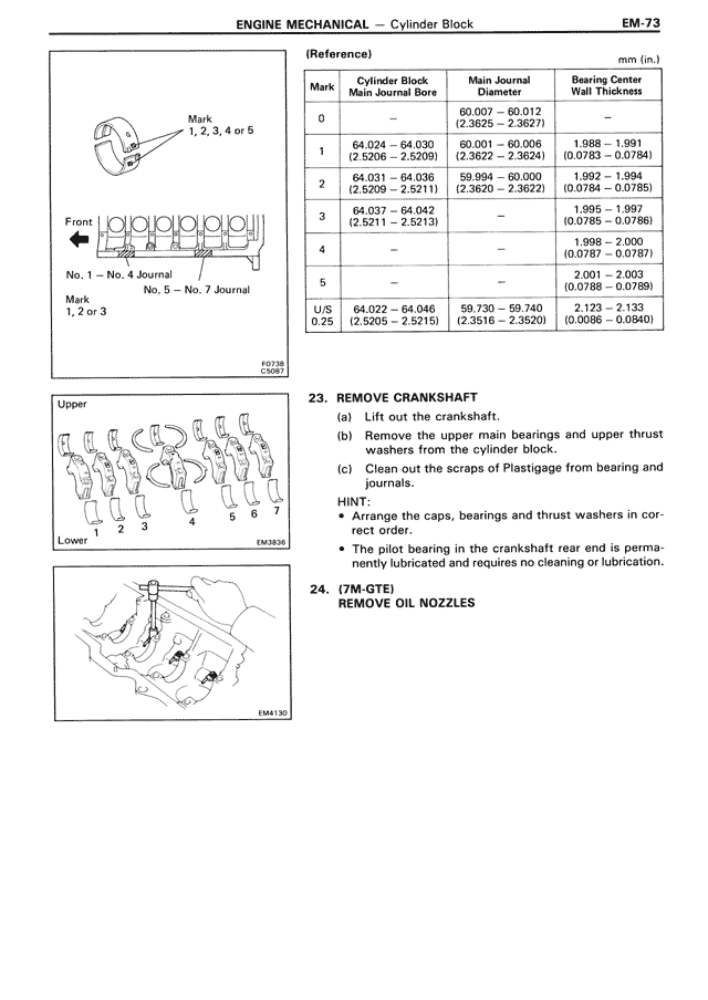
23. REMOVE CRANKSHAFT

    (a)  Lift out the crankshaft.
    (b)  Remove the upper main bearings and upper thrust
         washers from the cylinder block.
    (c)  Clean out the scraps of Plastigage from bearing and
         journals.

HINT:
  • Arrange the caps, bearings and thrust washers in cor-
    rect order.
  • The pilot bearing in the crankshaft rear end is perma-
    nently lubricated and requires no cleaning or lubrication.

24. (7M-GTE)
    REMOVE OIL NOZZLES

[DIAGRAM SHOWING OIL NOZZLE REMOVAL]
                                                            EM4130